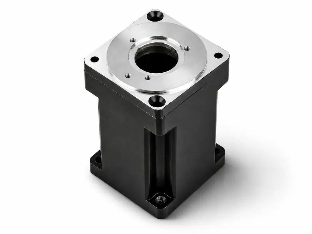
Square-Flange Servo Housing
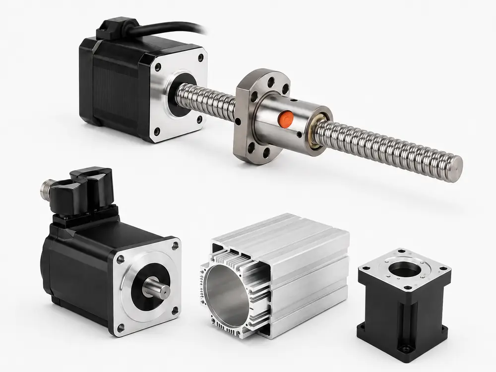
40–180 mm flange reference; four-corner mounting with drawing-defined front pilot and flange geometry. Runout can be reviewed to ≤0.01 mm where specified.
DRAWING-BASED SERVO HOUSING SUPPLY
Drawing-based aluminum servo motor housings built around the front flange, stator bore and rear feedback datum. Encoder, brake, connector and cooling interfaces are reviewed together so the finished housing supports the required alignment, assembly fit and thermal path.










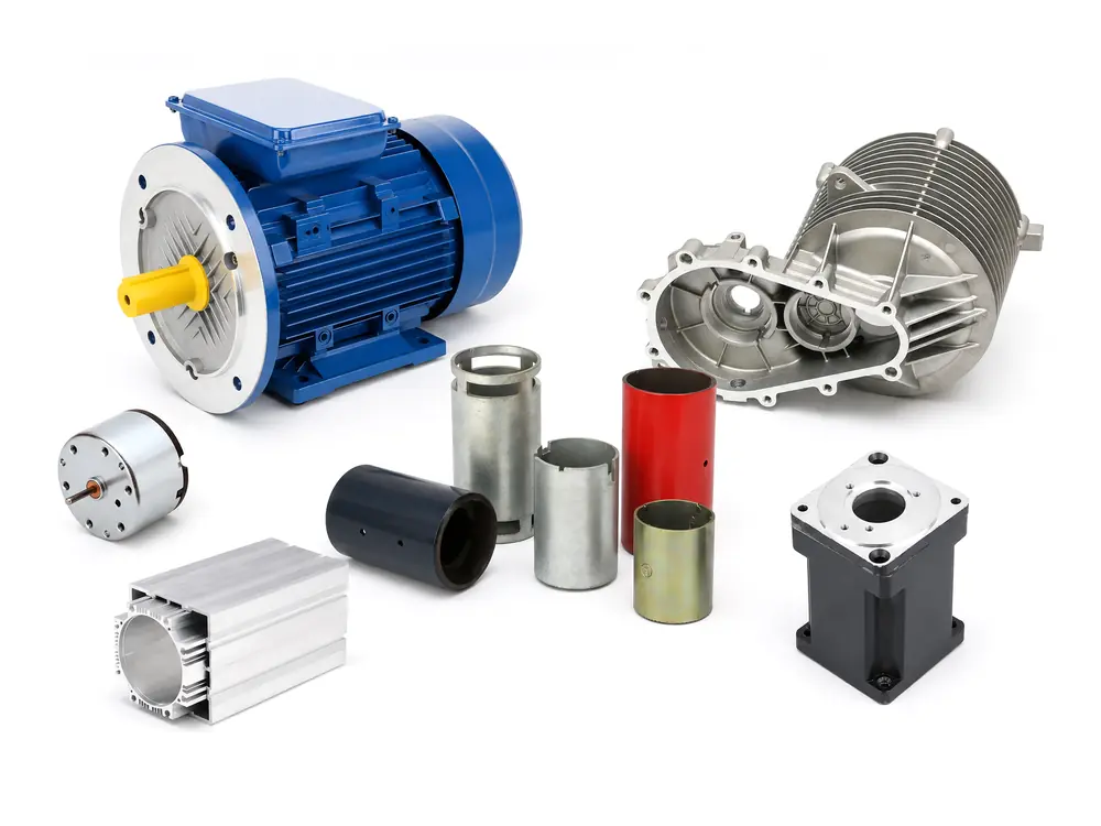
Product routes
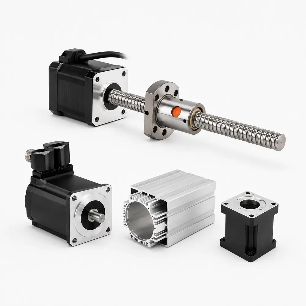
Servo housing architecture is selected around flange geometry, motor stack, feedback package, cooling path, mounting orientation and the dynamic loads created by repeated acceleration and reversal.
Before quotation
Send the drawing, servo interface requirements, operating conditions and expected volume together. A complete RFQ package helps us review machining, feedback interfaces and inspection requirements with fewer clarification rounds.
Technical parameters for quotation
Use these parameters to align housing geometry, servo datums, feedback interfaces, thermal requirements and inspection before quotation. Reference ranges support RFQ review; final values apply only after confirmation in the released drawing, approved specification and acceptance plan.
| Parameter group | Project-specific review basis | Release basis |
|---|---|---|
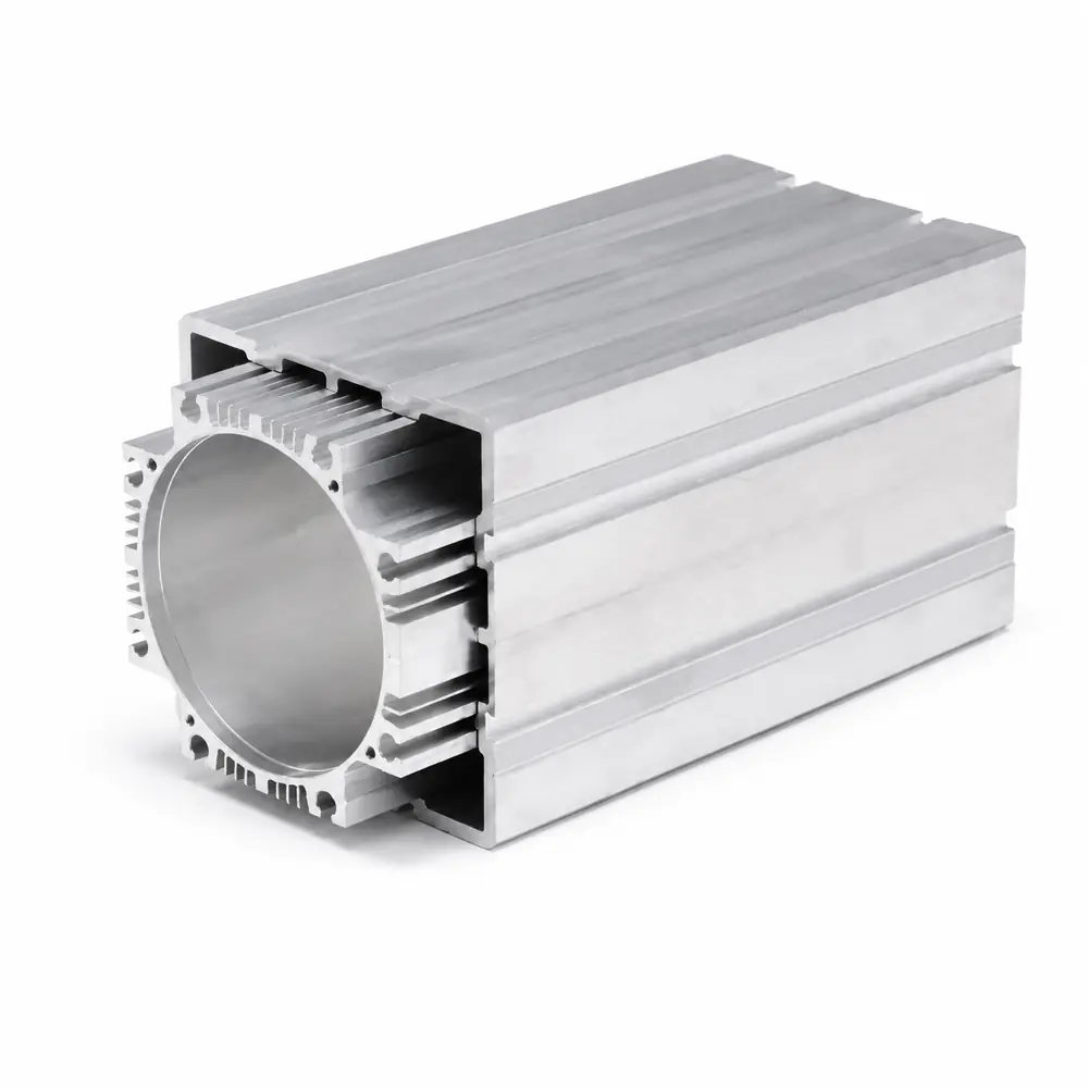
| Material / Process Route | 6063-T5 extrusion or ADC12 casting reference; extrusion, casting or machining route selected around housing geometry, volume and thermal duty. | Released material specification and approved manufacturing route. |
| Housing Envelope / Mounting | Flange reference 40–180 mm and housing-length review band 40–300 mm; mounting pattern, front pilot and connector orientation follow the mating servo package. | Released 2D/3D drawing and mechanical interface envelope. |
| Servo Alignment / Critical Fits | Stator fit H7/H8 reference; coaxiality or TIR 0.02–0.05 mm and flange perpendicularity 0.02–0.05 mm / 100 mm where specified. | Released GD&T, datum scheme and agreed inspection method. |
| Encoder / Brake Interfaces | Rear pilot, encoder or resolver envelope, holding-brake clearance, connector position and cable exit are reviewed as part of the rear feedback datum. | Released feedback-device drawings and interface specification. |
| Thermal / Surface Requirements | Cooling path, grounding and thermal-contact faces, masking and coating; specified machined surfaces may reference Ra 0.8–1.6 μm, with hard anodizing 25–50 μm where required. | Released finish specification, masking drawing and thermal-interface requirements. |
| Inspection / Acceptance | CMM, bore/roundness, flange runout, rear-datum and surface checks selected according to critical characteristics; IP targets are validated at assembled-motor level. | Approved sample baseline, inspection plan and defined acceptance limits. |
| Supply Boundary | Machined housing, finished housing, or drawing-defined encoder/brake interface hardware and mechanical subassembly only when included in the quotation. | Released BOM and quoted supply scope. |
SERVO PACKAGE DEFINITION
GX reviews the front mounting flange, stator bore, bearing axis, rear pilot and encoder or brake interface as one connected geometry. Project references may include H7/H8 stator fits, 0.02–0.05 mm coaxiality or TIR, and flange perpendicularity of 0.02–0.05 mm per 100 mm where specified.

DATUM-BASED MACHINING
The machining sequence is built around a released datum strategy rather than independent dimensions. After blank stabilization, critical bores, pilots and mounting faces are machined with controlled re-clamping, followed by masking and surface finishing. Specified interfaces may be reviewed to Ra 0.8–1.6 μm, while hard-anodized surfaces can use 25–50 μm project reference thickness where required.

EVIDENCE BEFORE REPEAT ORDERS
Sample approval should verify the finished housing—not only the pre-finish machined part. CMM, gauges and surface measurement can confirm flange-to-bore alignment, rear feedback datums, critical fits and protected interfaces after finishing. The approved results then establish the baseline for recurring production.
Final values apply to production only after confirmation in the released drawing, approved specification, quotation and acceptance plan.

Product and supply scope
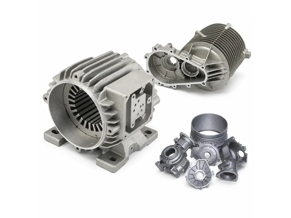
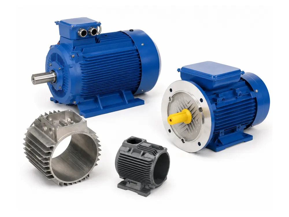
A servo motor housing is the precision structural body that links the front mounting flange, stator bore, bearing axis and rear feedback interface into one alignment chain. Unlike a general motor enclosure, it must maintain these relationships through repeated acceleration, reversal and thermal cycling while also supporting heat transfer, encoder or brake packaging and connector access. Critical interfaces may be reviewed to H7/H8 stator fits and 0.02–0.05 mm coaxiality or TIR where specified. GX supplies drawing-defined machined or finished servo housings and specified mechanical subassemblies; encoders, brakes, bearings, windings and electronics are included only when listed in the approved BOM.
Project route
The manufacturing route links blank preparation, stabilization, datum setup, critical machining and surface finishing so the front flange, stator bore and rear feedback interface remain tied to one machining strategy.

Review motor stack, flange, stator bore, rear feedback package, brake, connector and cooling envelope before the route is fixed.
Select extrusion, casting or billet machining around geometry, housing length, thermal duty and expected volume.
Cut, inspect and stabilize the aluminum blank before critical machining where the material and process require it.
Establish the setup linking the front flange, stator bore and rear pilot before precision features are machined.
Machine the flange pilot, stator bore, bearing-related interfaces and rear feedback datum from the released setup strategy.
Deburr, clean, mask precision fits and apply anodizing or coating while protecting grounding and thermal-contact surfaces.
Verification
Verification connects the front mounting flange, stator bore, rear pilot and feedback-system interfaces to the same released datum scheme used for the servo assembly.

| Control item | Method / evidence | Buyer benefit |
|---|---|---|
| Flange / Front Pilot | CMM, height gauge and dedicated fixtures for flange face, pilot diameter, position and perpendicularity. | Controls motor mounting position and front-end alignment. |
| Stator Bore / Rear Datum | Bore gauge, roundness equipment and CMM for stator bore, rear pilot, coaxiality and TIR where specified. | Maintains the front-to-rear servo alignment chain. |
| Encoder / Brake Interfaces | Positional inspection, thread gauges and dedicated fixtures for encoder, brake, connector and cable-exit interfaces. | Prevents feedback-package, brake and connector assembly interference. |
| Surface / Protected Fits | Roughness, coating-thickness and masking checks on precision fits, grounding faces and thermal-contact surfaces. | Protects precision fits, electrical grounding and heat-transfer interfaces. |
| Assembly Evidence | Gauge or trial-fit verification using agreed stator, end-cover, encoder or brake interfaces where required. | Confirms the measured geometry translates into the intended assembly condition. |
Application fit
Application requirements are driven by motion accuracy, dynamic load, thermal duty and feedback interfaces—not by housing geometry alone.
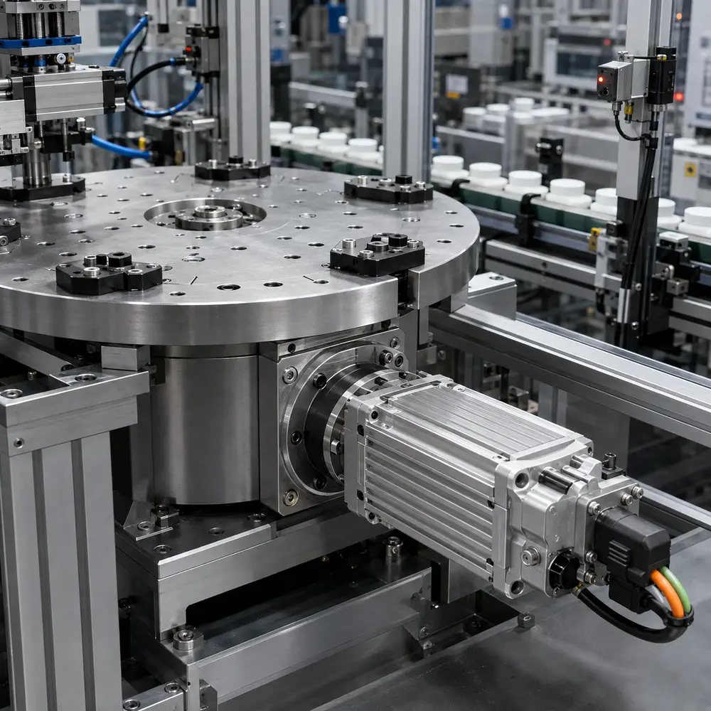
Frequent indexing and reversal require stable flange-to-stator alignment. H7/H8 stator fits and 0.02–0.05 mm coaxiality or TIR can be reviewed where specified.
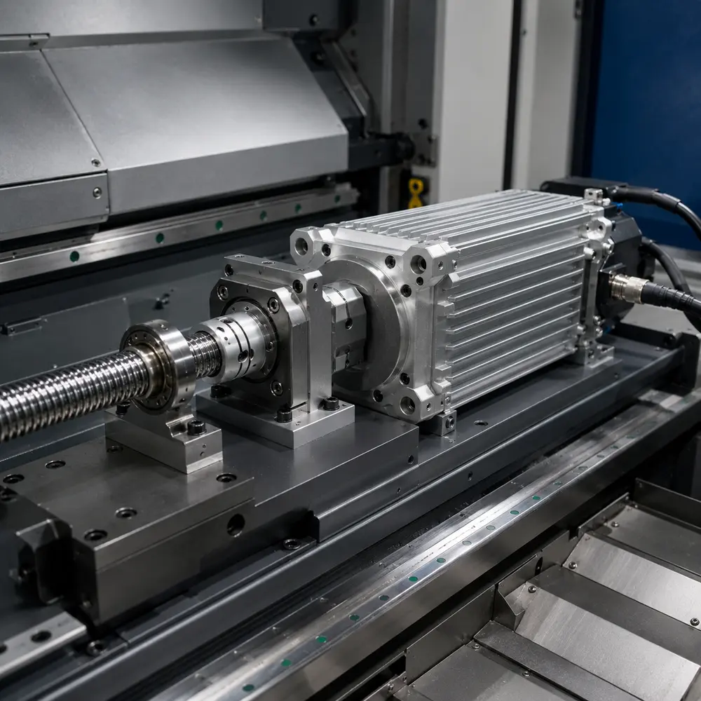
Feed axes depend on flange accuracy and thermal stability. Flange perpendicularity may be reviewed at 0.02–0.05 mm / 100 mm, with critical runout ≤0.01 mm where specified.

Compact housings must balance low mass, rigidity and rear feedback packaging under repeated acceleration. Encoder, brake and connector interfaces are controlled from the servo datum chain.
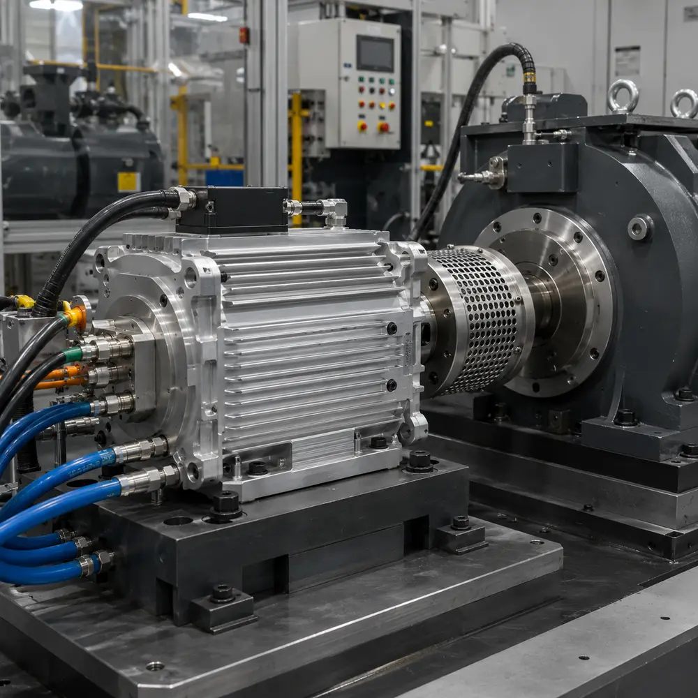
Continuous load raises thermal and bearing-alignment demands. Cooling paths, thermal-contact faces and critical machined surfaces can be reviewed to Ra 0.8–1.6 μm where specified.
Project control
GX coordinates revision, material, process, sample approval, critical-characteristic inspection and recurring records according to the project scope. Certification claims are limited to their documented company and product scope.
Housing material, front and rear datums, encoder or brake interfaces, surface finish, supplied components and acceptance criteria follow the current released drawing and BOM.
Flange geometry, stator-bore fit, rear feedback datum, surface condition and agreed trial-fit results are recorded to establish the approved production baseline.
Defined gauges, fixtures, inspection frequency and acceptance limits are carried into recurring production. Where process capability is specified, Cpk ≥1.33 can be used as the reference target for defined critical characteristics.
Project evidence is defined during quotation and may include material records, CMM or dimensional reports, flange runout, stator-bore geometry, rear-datum results, surface roughness, coating and marked-drawing inspection records.
Engineering and sourcing FAQ
Eight practical questions covering servo datum definition, critical fits, encoder and brake interfaces, surface requirements, inspection and repeat production.
The difference is determined by motor architecture, load path, bearing arrangement, cooling and manufacturing route. Compare the drawing interfaces and validation requirements rather than choosing by frame appearance alone.
Review cast or extruded aluminum route, machining allowance and thermal requirement. The selected route must support the required datum structure, machining access, thermal behavior, surface treatment and projected volume.
The critical dimensions are those controlling rotor-stator alignment and final assembly. Typical review points include bearing bores, mounting datums, concentricity, face runout and encoder interfaces, but the customer drawing must identify the functional datum scheme and inspection priority.
Control them from a consistent machining datum and verify the relationship, not only each size independently. The acceptance plan should define bore size, position or concentricity, face runout and the gauge or CMM method.
Testing is required when the housing forms a sealed cavity, coolant path or specified environmental barrier. Define surface finish, sealing, leakage criteria, thermal path and service environment, test pressure or method, allowable leakage and the surfaces included in the test boundary.
Inspection should combine material or casting checks with critical machined dimensions, datum relationships, thread and surface-condition checks. Coating thickness, cleanliness, leakage or packaging controls are added only when the released specification requires them.
Provide 2D drawings and 3D data, material and process preference, bearing bores, mounting datums, concentricity, face runout and encoder interfaces, surface finish, sealing, leakage criteria, thermal path and service environment, annual quantity and acceptance method. Identify supplied inserts, machining scope, surface treatment and any required test fixtures.
Agree the drawing revision, datum strategy, critical-characteristic list and inspection method before production approval. The first-article package should record results and approved deviations; recurring supply follows the released drawing, quotation and control plan.
Request for quotation
Send 2D/3D files, mating interfaces, material and process requirements, operating limits, surface finish, sample quantity, annual demand and validation expectations.