
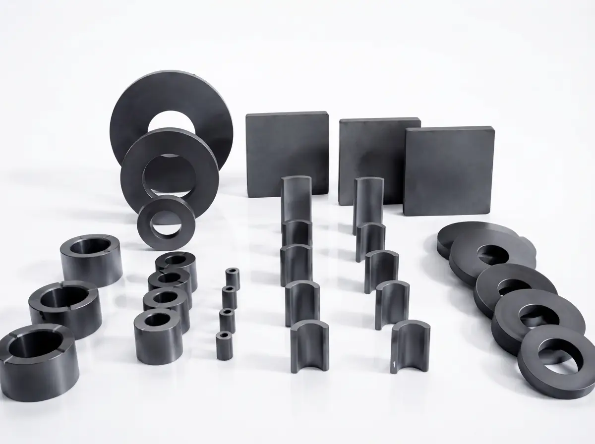

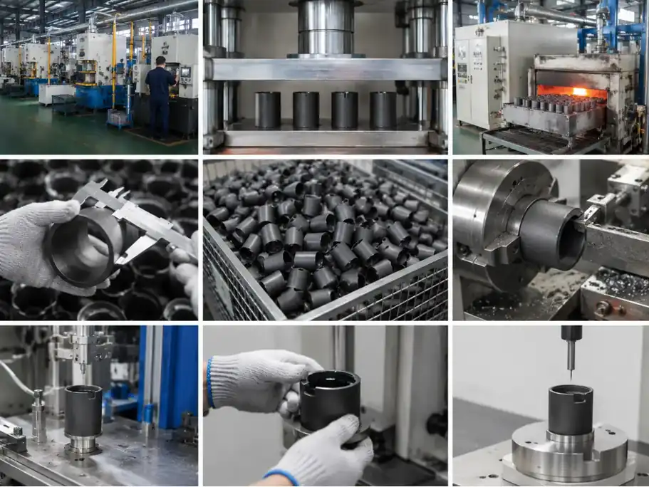
Shape and Dimensions
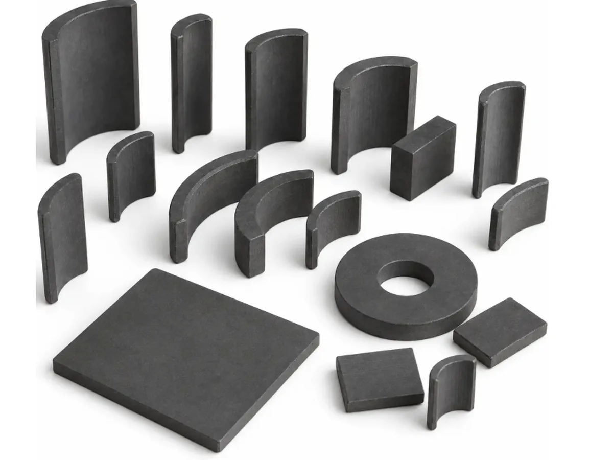
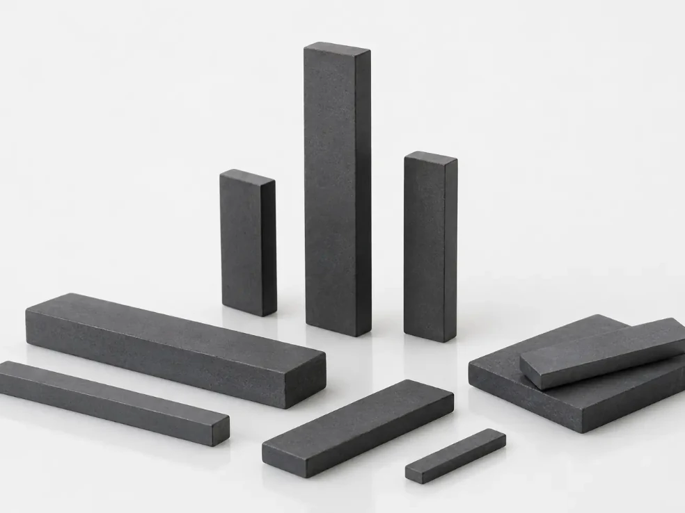
Ring, arc, block, bar and feasible drawing-defined forms are reviewed with wall section, radii, length-to-section ratio and installed clearance.
Ferrite Magnet
GX Magnet manufactures custom sintered ferrite rings, arcs, blocks, bars and drawing-specific shapes for motors, pumps, sensors, magnetic separation equipment and other OEM magnetic systems. In-house powder preparation, wet or dry pressing, sintering, grinding and magnetization are selected to match the required geometry, material orientation and magnetic target. Critical dimensions and finished-part magnetic output are verified before sample approval and controlled throughout recurring production.









Before quotation
These four inputs allow GX to assess manufacturability, match the part with suitable tooling and applicable automated production processes, and confirm the material, finishing and inspection scope behind the quotation.
QUICK PRODUCT SELECTION
Match the assembly geometry and required magnetic function to the product families below. Each category summarizes its available forms and typical applications, helping engineers quickly identify the relevant product page for further review.
Why choose us for your project
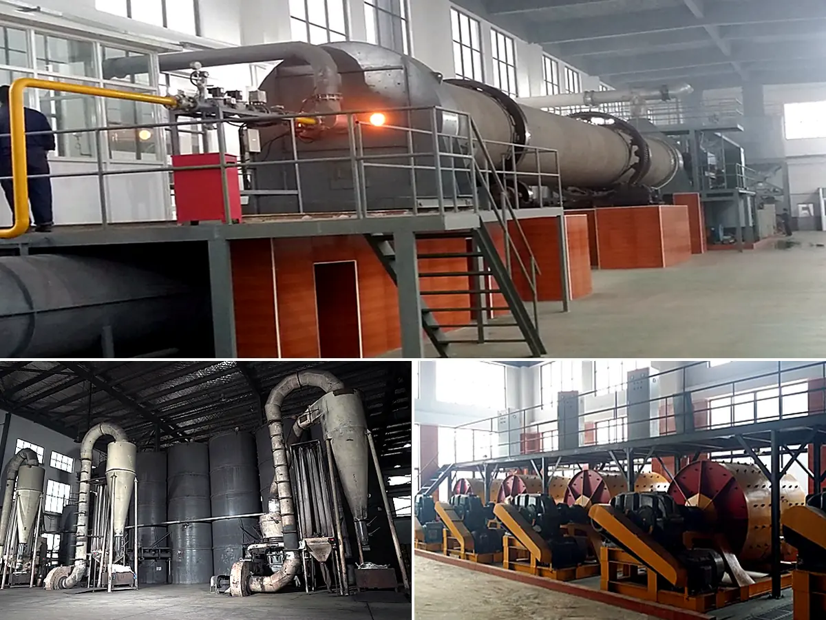
GX prepares ferrite powder for its own magnet production through pre-sintering, Raymond milling, air classification and ball milling. The recorded classification route centers the particle distribution around 2μm before milling with 4mm media, providing a controlled material basis for pressing, orientation and sintering.
FORMING AND SINTERING ROUTES
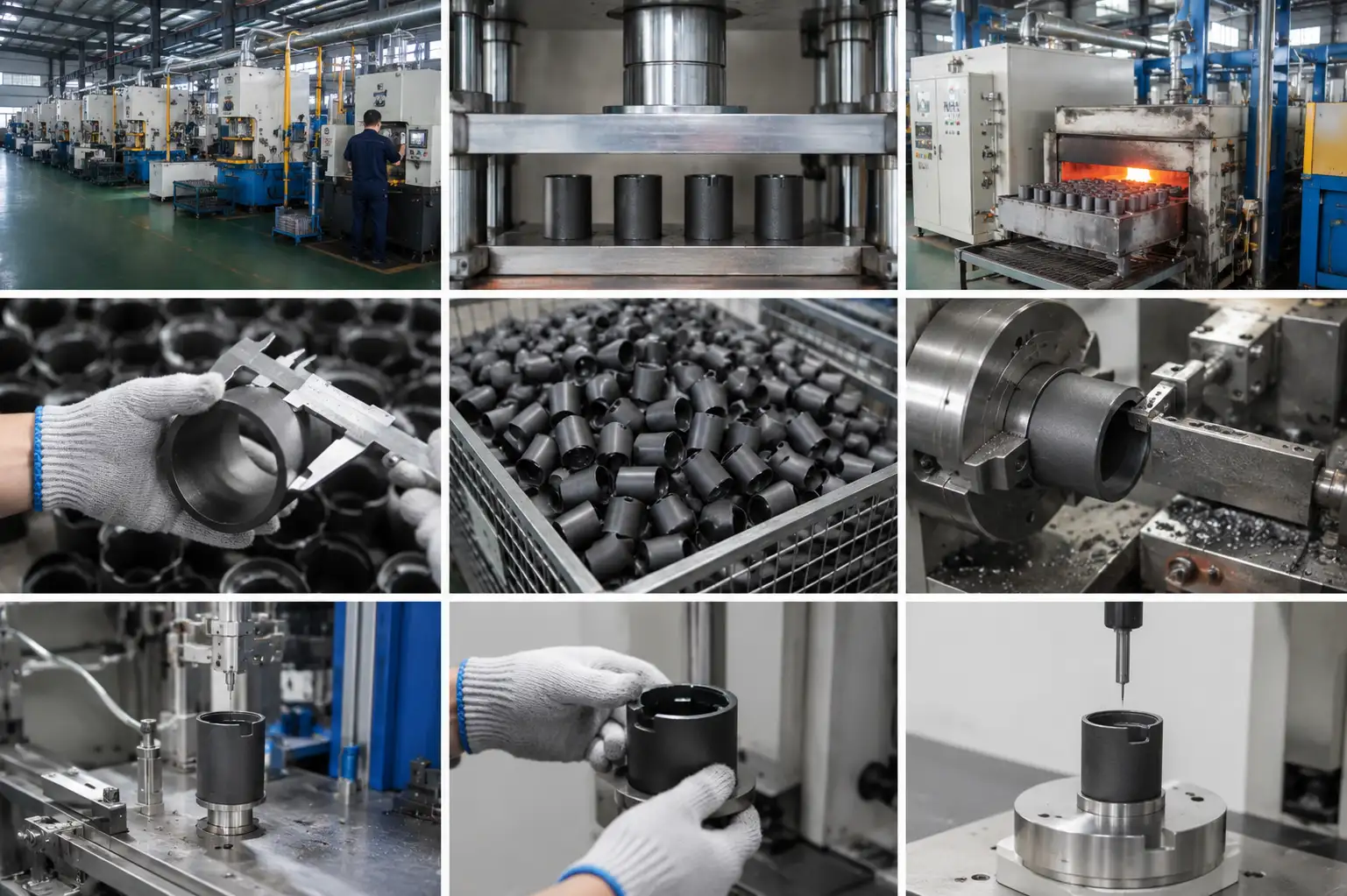
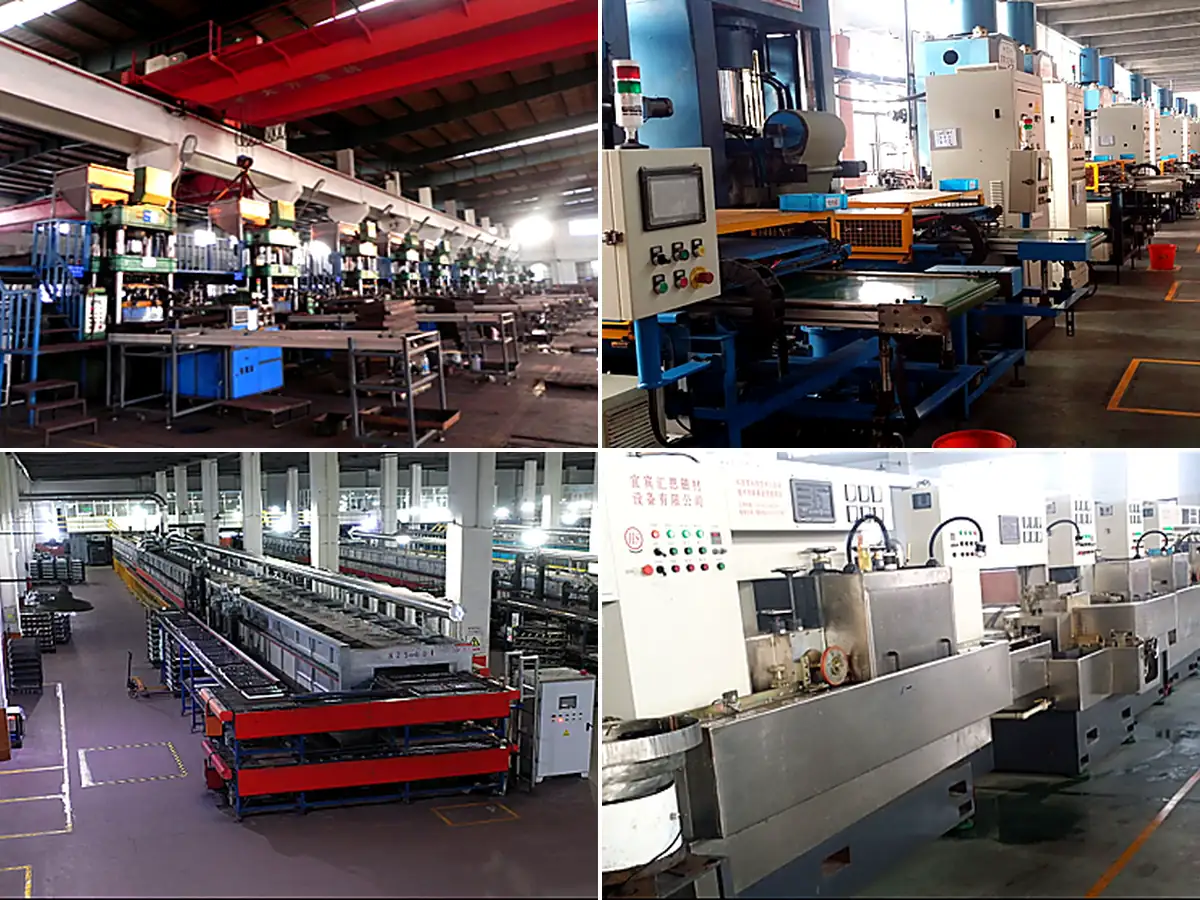
GX reviews geometry, magnetic orientation, integrated features and production demand before selecting wet pressing, dry pressing or injection molding. For sintered parts, forming conditions are connected to dehydration, shrinkage and final geometry through the double-layer kiln route.
TOOLING, FINISHING AND AUTOMATION
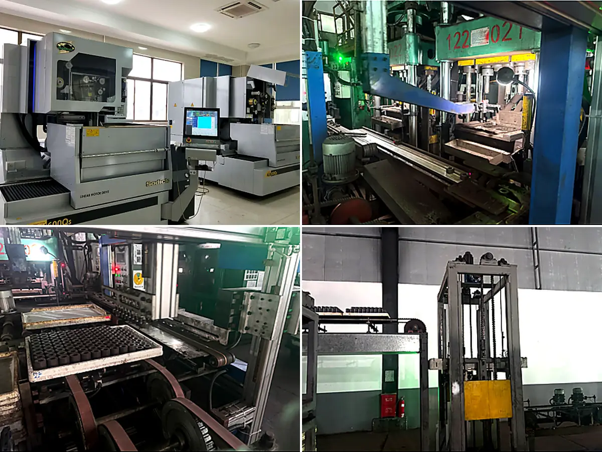
GX coordinates tooling, sintering shrinkage, grinding, magnetization, cleaning and inspection around the released drawing. Recorded products range from 2.2mm-thick ferrite arcs weighing approximately 4.9g to large motor arcs of approximately 300–850g.
Final values are binding for supply only after formal confirmation of released drawing, approved specification, quotation and acceptance plan.
VALIDATED PROGRAM PERFORMANCE
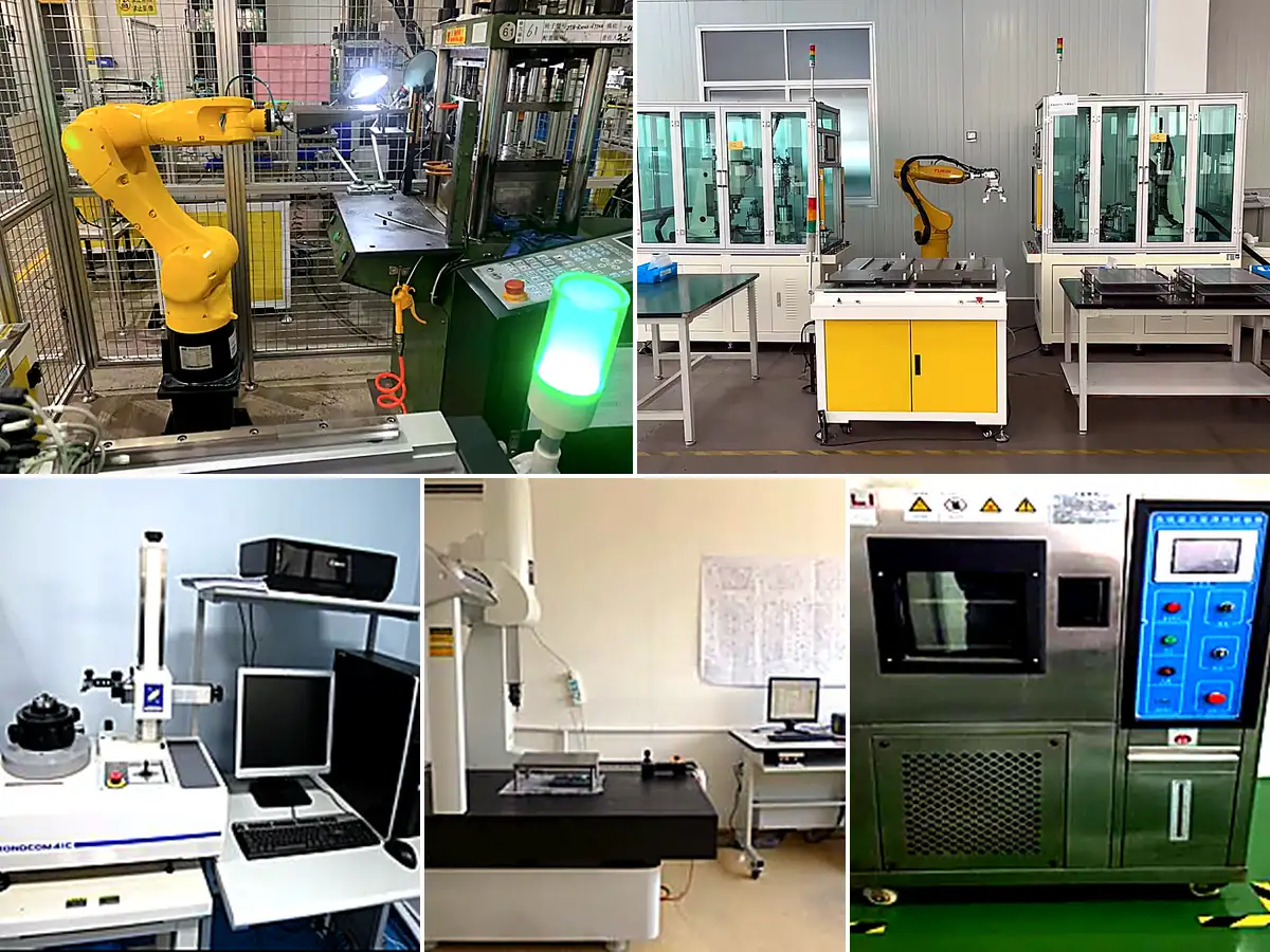
GX verifies drawing-defined dimensions, polarity, field, flux or waveform under agreed measurement conditions before recurring production. Environmental and functional tests are added when required, while approved samples and measurable criteria provide the basis for lot-to-lot control.
PRODUCT DEFINITION AND SUPPLY SCOPE
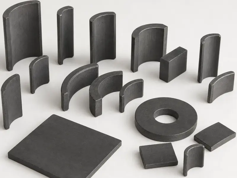
A custom ferrite magnet is a sintered hard-ferrite permanent magnet manufactured to a customer drawing when the assembly requires a specific shape, interface, magnetic orientation or finished-part output. Rings, arcs, segments, blocks, bars and other drawing-defined forms can be developed for motors, pumps, sensors, speakers, holding devices and magnetic-separation systems.
GX reviews the geometry, working air gap, material grade, magnetization, operating conditions and inspection method as one specification. Unless otherwise stated in the quotation, the supply scope covers the sintered magnet; back plates, holders, adhesives and final assemblies are reviewed separately.
Customization boundary
Customization starts from the installed magnetic function, not from shape alone. GX reviews the drawing, magnetic circuit, acceptance method and supply boundary before confirming what can be sampled.
Ring, arc, block, bar and feasible drawing-defined forms are reviewed with wall section, radii, length-to-section ratio and installed clearance.
Specify the applicable grade system or required Br, Hcb, Hcj, BHmax or assembly-level magnetic response with its test method.
Define pole faces, direction, pole count or polarity sequence together with the installed orientation and magnetic acceptance position.
Identify the working face, bonding face and inspection datum; apply tight limits only where they control fit, air gap or magnetic function.
Holes, slots, steps, chamfers and fragile corners require manufacturability review before they are included in a released sintered ferrite drawing.
Confirm the measured parameter, fixture, sample approval and whether supply ends at the loose magnet or includes a separately evaluated component.
TECHNICAL PARAMETERS FOR RFQ
Review the material, geometry, magnetic function, assembly interface, operating conditions and acceptance method as one project specification. Final requirements are confirmed through the released drawing, approved sample, quotation and inspection plan for recurring production.
| Parameter group | Project-specific review basis | Confirmation and Release Basis |
|---|---|---|
| Material / route | Sintered strontium ferrite; GX grades F5B, FB6N, FB7N, FB9N, FB12B or FB13B. Grade, isotropic or anisotropic condition and pressing route are selected for the geometry, field direction and operating conditions. | Approved grade and orientation recorded in the released specification; Br, Hcb, Hcj and (BH)max report at 20°C when specified. |
| Geometry and tolerances | Ring, arc, segment, block, bar or feasible drawing-defined form. Define OD, ID, length, thickness, working faces, datums, tolerances and edge requirements as applicable. | Released drawing defines dimensions, datums and tolerances; the first-article dimensional report verifies conformity. |
| Magnetic or functional requirement | Define magnetic orientation, magnetization direction, polarity or pole pattern and the required finished-part flux, surface field, pull force or functional response. | Approved sample report records the acceptance limits, measurement air gap, position, fixture and temperature. |
| Mechanical / assembly interface | Review locating and mating dimensions, bonding or press-fit surfaces, carrier features, installed orientation and retention requirements. | Assembly drawing confirms the interfaces; fit, bonding or retention testing is completed when specified. |
| Operating environment | Specify operating temperature, moisture, vibration, impact, contact medium and any external demagnetizing field relevant to the application. | Validation plan defines the applicable exposure conditions, test duration and acceptance criteria. |
| Inspection and acceptance | Agree dimensional, visual, material-property and finished-part magnetic inspections under defined measurement conditions. | Control plan defines the method, gauge or fixture, sample size, inspection frequency and lot-release records. |
| Supply boundary | Define whether GX supplies the sintered magnet only or also includes grinding, magnetization, inspection, packaging, documentation or quoted assembly items. | Quotation and released drawing identify all supplied components, processes and documentation. |
| GX grade | Br (Gs) | Hcb (Oe) | Hcj (Oe) | (BH)max (MGOe) |
|---|---|---|---|---|
| FSB | 4,200 ± 100 | 3,300 ± 150 | 3,350 ± 200 | 4.0 ± 0.2 |
| FB6N | 4,300 ± 100 | 3,300 ± 150 | 3,350 ± 200 | 4.4 ± 0.2 |
| FB7N | 4,400 ± 100 | 3,300 ± 150 | 3,350 ± 200 | 4.6 ± 0.2 |
| FB9N | 4,600 ± 100 | 3,500 ± 200 | 3,600 ± 200 | 5.1 ± 0.2 |
| FB12B | 4,650 ± 100 | 4,300 ± 200 | 4,850 ± 200 | 5.2 ± 0.2 |
| FB13B | 4,750 ± 100 | 4,300 ± 200 | 4,850 ± 200 | 5.3 ± 0.2 |
These values describe the material grade. Finished-part output depends on geometry, orientation, magnetization, temperature, magnetic circuit and measurement conditions.
MANUFACTURING ROUTE SELECTION
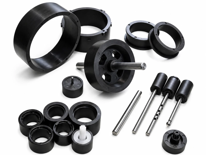
Sintered ferrite is suited to pressed and finished magnet forms, while injection-molded ferrite supports complex molded geometry and integrated features. GX reviews the part geometry, magnetic output, assembly interface, production volume and acceptance criteria before confirming the appropriate project route.
| Decision point | Sintered Ferrite | Injection-Molded Ferrite |
|---|---|---|
| Geometry | Rings, arcs, segments, blocks and bars produced by pressing and sintering, with grinding applied to drawing-defined dimensions or working faces when required. | Complex molded profiles, thin sections, locating features and other integrated geometry formed within the molding process. |
| Magnetic Requirement | Ferrite grade, isotropic or anisotropic orientation, magnetization direction and finished-part magnetic limits are defined for the sintered magnet. | Ferrite-polymer compound, magnetic orientation, pole pattern and molded-part magnetic output are defined for the application. |
| Assembly state | Supplied as an individual magnet for bonding or mechanical retention, or as part of a separately quoted assembly scope. | Insert molding or overmolding can integrate a shaft, hub, sleeve or locating feature when confirmed during project review. |
| Tooling and Production Volume | Pressing tooling, grinding requirements and magnetizing or inspection fixtures are evaluated against the geometry and recurring demand. | Mold design, inserts, compound flow, molded shrinkage and expected production volume are evaluated as one manufacturing route. |
| Information for Review | Provide the drawing, material grade or magnetic target, working faces, magnetization direction, tolerances, operating conditions and demand. | Provide the 3D drawing, resin or environmental requirements, inserts, critical molded dimensions, pole pattern, acceptance criteria and demand. |
ENGINEERING CHANGE PROCESS
When the drawing, material, magnetic target, assembly interface or acceptance criteria change, GX compares the new requirements with the current approved version. The impact is reviewed, affected characteristics are revalidated, and the revised specification is introduced into recurring production only after approval.
Provide the updated drawing or specification with a new revision number. Clearly identify changes to geometry, material, magnetization, interfaces, inspection criteria and the requested implementation timing.
GX compares the revision with the approved production basis and reviews its effect on tooling, pressing, sintering, grinding, magnetization and inspection. Updated samples, dimensions or magnetic results are submitted for approval when required.
After the revised drawing, sample and acceptance criteria are approved, GX updates the applicable production and inspection documents and confirms the effective batch. Recurring production then follows the released revision.
Application review
Each application is reviewed against its assembly geometry, magnetic function and operating conditions. Final dimensions, magnetization and acceptance limits are confirmed through the approved drawing and sample.

Custom ferrite magnets support motors, actuators and positioning mechanisms. Review the air gap, mounting interface, polarity, magnetic output, temperature and vibration, then verify critical dimensions and magnetic response during sample approval.
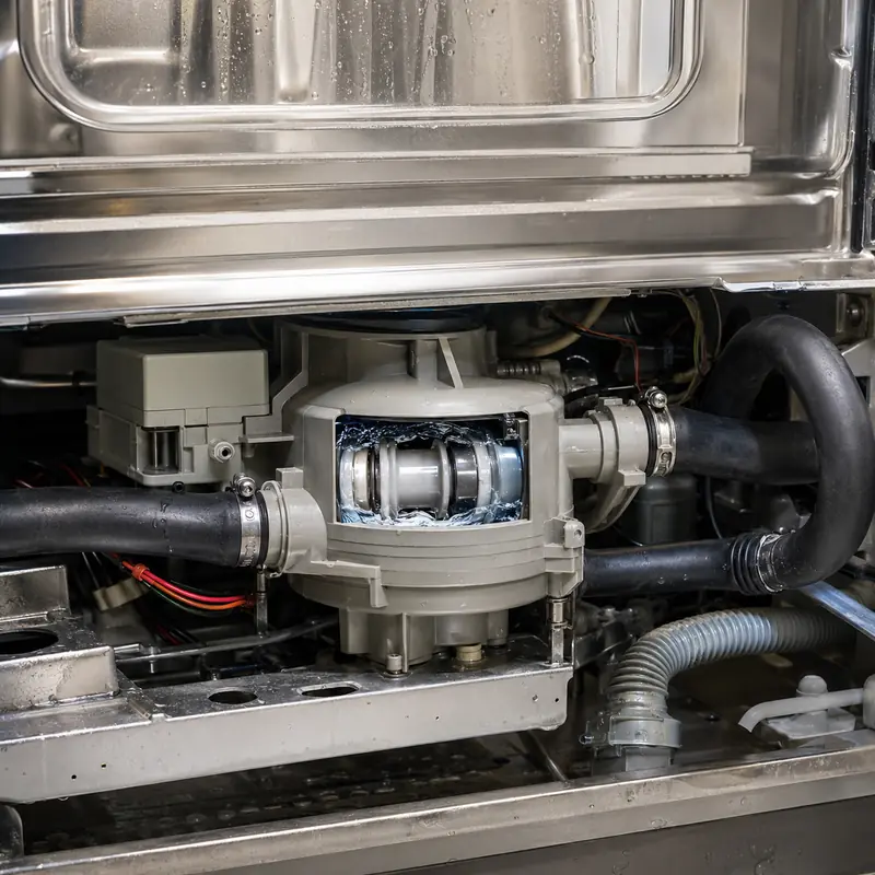
For circulation, drainage and cooling pumps, match the magnet geometry to the rotor or carrier, working air gap and retention method. Validate magnetic output, medium exposure, thermal cycling and assembly fit against the approved sample.

Ferrite magnets can be developed for automotive pumps, fans and actuators. Define geometry, polarity, magnetic output and retention from the assembly, then verify critical dimensions, temperature and vibration requirements before recurring production.
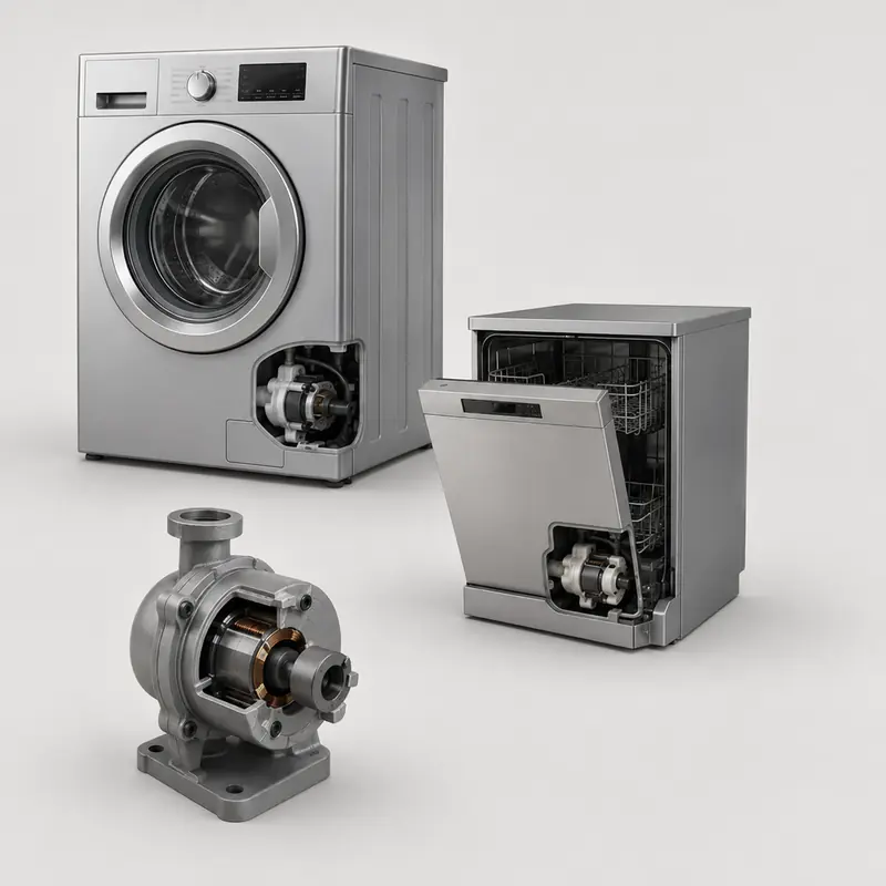
For washing machines, dishwashers, fans and other appliance motors, match the magnet to the housing, air gap and mating component. Confirm magnetic response, installation dimensions and applicable moisture or temperature conditions during sample approval.
Customer and industry presence
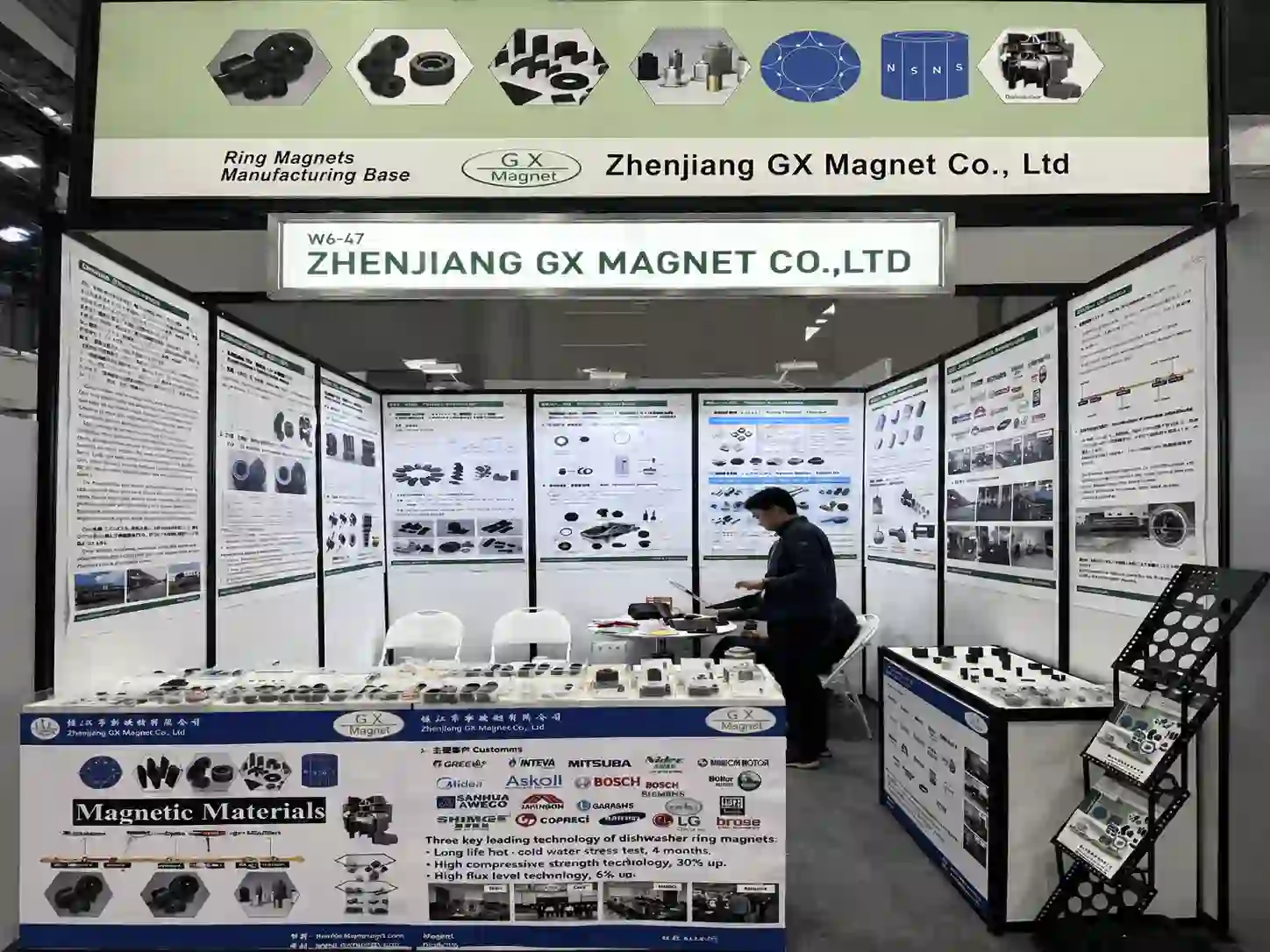
GX Magnet at magnetic-material and motor-component industry exhibitions.
GX Magnet Booth at Manufacturing World Tokyo 2026. Event or visit photograph documenting the people and setting shown.
Documented evidence
GX adopts documented quality‑system controls together with ferrite sample compliance reports as supporting evidence. Product drawings and agreed inspection specifications serve as the formal release basis for every custom magnet project.
Zhenjiang GX Magnet Co., Ltd. holds valid IATF 16949:2016 certification for permanent ferrite component manufacturing.
SGS RoHS compliance test report confirms the submitted ferrite magnet sample passes EU RoHS screening requirements.
SGS REACH SVHC test report confirms the submitted magnet sample passes screening for REACH SVHC candidate‑list substances.
ENGINEERING AND SOURCING FAQ
Eight critical points covering material selection, drawing specification, performance verification and production approval for custom ferrite magnet projects.
The main differences are the material route, achievable geometry, magnetic output and assembly method. Compare them in the actual magnetic circuit and operating condition; the product name alone is not enough to select the part.
Start with strontium-ferrite grade and isotropic or anisotropic orientation. Then check the required magnetic output, geometry, temperature and commercial volume before fixing a grade in the drawing.
Control the dimensions that set fit, air gap or working position. For this product, review dimensions, tolerances, magnetization direction and magnetic target; avoid applying a tight general tolerance to non-functional surfaces without a measurement reason.
Specify the magnetization axis or pole pattern, pole count where applicable, and the acceptance method. A field value must also state the measurement location, fixture or air gap so supplier and buyer evaluate the same condition.
Temperature capability depends on material grade, geometry, magnetizing state and the magnetic circuit. Provide working temperature, medium or corrosion environment and magnetic-circuit condition; GX can then review demagnetization risk and whether the proposed material route fits the duty.
Use an agreed method tied to the application: material-property testing, surface field at a defined position, flux, pull force, pole pattern or waveform. The released drawing and acceptance plan should state the instrument, fixture and limits.
Send the drawing or 3D model, material or magnetic target, dimensions, tolerances, magnetization direction and magnetic target, working temperature, medium or corrosion environment and magnetic-circuit condition, expected quantity and acceptance method. State whether tooling, inserts, assembly or magnetization is included in the requested supply scope.
Agree the drawing revision, tooling state, critical dimensions and magnetic test method before sample release. Approval should identify the sample record and any deviations; recurring orders then follow the released specification, quotation and control plan.
Project inquiry
Attach the part and assembly drawings. GX reviews custom geometry, material or magnetic target, magnetization, application conditions and inspection method before defining the sample route.