

Magnetic Material
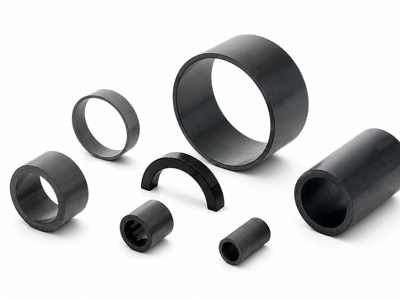
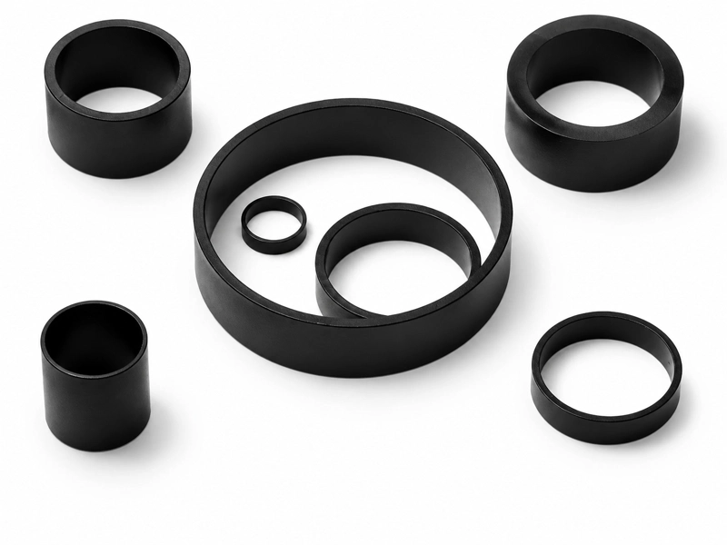
Ferrite and NdFeB bonded systems are evaluated against your flux density, cost target, operating temperature and geometry. Binder options include PA12, PA6 and PPS, with continuous operating temperatures from 100 °C up to 150 °C.
INJECTION MAGNETS · CUSTOM PROJECT ROUTE
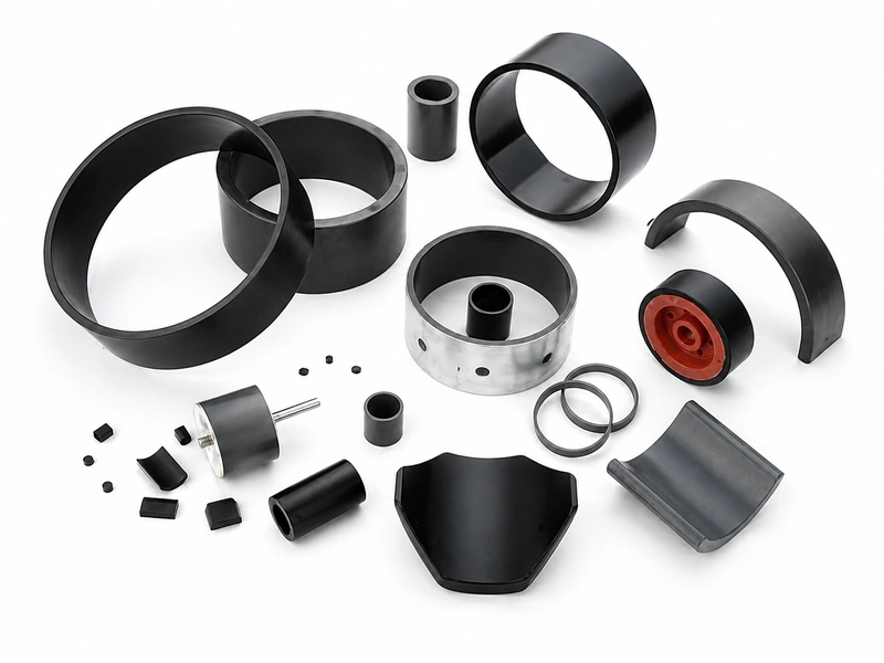
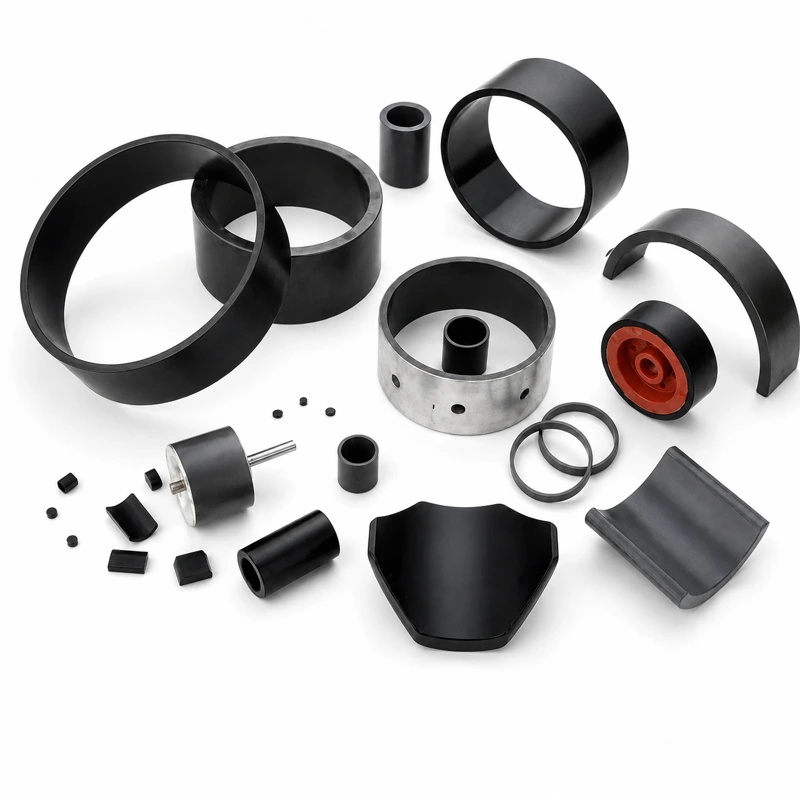
GX Magnet delivers drawing-driven custom bonded magnet solutions backed by 30+ years’ expertise and IATF 16949-certified production. We match your application with optimal material, forming process, inserts and magnetization across ferrite, NdFeB, injection and compression routes.









Before quotation
Backed by 30+ years of bonded magnet manufacturing expertise and IATF 16949-certified production, a complete consistent technical package enables accurate quoting, DFM assessment and first-time-right sample approval.
Product relationship
Use this product roadmap to navigate our complete portfolio of bonded and injection molded magnets. Filter by material chemistry, part geometry and forming process to quickly pinpoint the optimal manufacturing route, precisely aligned with your magnetic performance targets, operating conditions and production volume requirements.
Why choose us for your project
With 30+ years of bonded magnet formulation expertise, GX Magnet engineers ferrite and NdFeB magnetic compounds tailored to your performance, temperature and cost targets. We control every material variable — from magnetic powder grade to polymer binder — for consistent results from prototype to full production.
Process linked to the requirement
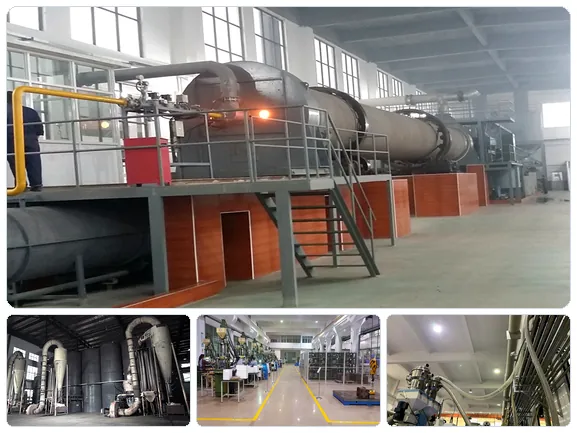
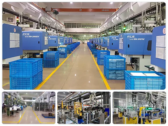
We engineer each manufacturing route around your part’s fit, form and functional requirements. Our workflow unifies compound preparation, DFM mold review, precision injection molding and controlled magnetization — with dedicated tooling, production fixtures and inspection checkpoints defined exclusively for your project.
Evidence before repeat orders
Every custom injection magnet program receives a part-specific validation package — not generic quality claims. Our release documentation includes full first article inspection, critical dimension reporting, magnetic performance verification and a dedicated control plan, built to IATF 16949 quality standards.
All supply commitments are formalized only after mutual alignment on released drawing revisions, approved specifications, pricing and acceptance criteria.
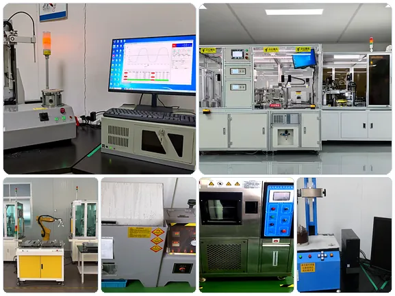
Process linked to the requirement
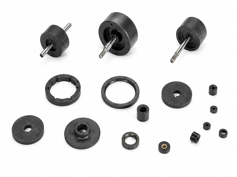
GX Magnet manufactures custom ferrite and NdFeB injection molded magnets backed by 30+ years of industry expertise. Our process integrates insert overmolding, complex geometries and 2–64 pole magnetization, delivering production-ready components matched to your assembly and performance specifications.

Product and supply scope
Use this route when the requirement is described as an injection magnet, bonded magnet, polymer-bonded magnet or molded magnetic component but the magnetic material, forming process or final structure has not yet been fixed. It is also the project route for injection molded magnetic rotor concepts that need joint material and assembly review.
GX evaluates bonded ferrite and bonded NdFeB options, including injection and confirmed compression-bonded routes. Bonded SmCo is excluded from GX supply. Final product scope is limited to the material, geometry, insert, magnetization and assembly items confirmed in the quotation.
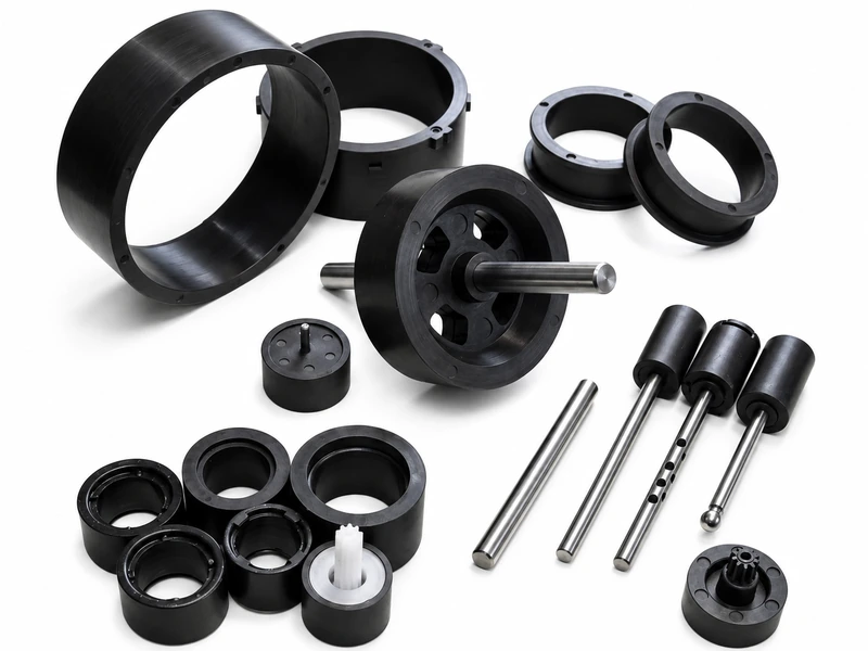
Drawing variables
Geometry, magnetic performance, forming process and assembly interface are engineered as one integrated component system to avoid downstream fit and function issues.
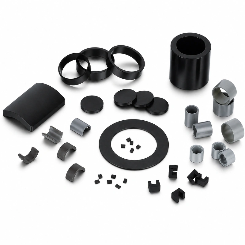
Technical parameters for quotation
This table standardizes technical inputs for quotation review. Reference ranges are for preliminary evaluation only; formal supply commitments are finalized upon confirmed drawing revisions, approved specifications, pricing and acceptance criteria.
| Parameter group | Project-specific review basis | Release basis |
|---|---|---|
| Material / route | Injection-molded ferrite or NdFeB compound with project-specified binder (PA12 / PA6 / PPS); powder loading 65–90 wt%, continuous operating temperature 100–150 °C; final formulation subject to approval | Approved material grade specification, released formulation drawing and sample magnetic performance test record with batch traceability. |
| Geometry and tolerances | Molded walls (down to 0.3 mm), ribs, holes, inserts, hubs, shrinkage datums, critical tolerances (as tight as ±0.03 mm), concentricity and runout specifications | Released production drawing, defined dimensional inspection method, certified gauging and full first-article inspection (FAI) report with Cpk data. |
| Magnetic or functional requirement | Magnetic compound grade, plus finished-part surface field, flux density, 2–64 pole pattern (±1° placement accuracy) or output waveform, measured at specified air gap and test conditions | Approved magnetic test method, calibrated fixture, specified measurement air gap & temperature, and accepted flux / waveform / pole placement tolerance limits. |
| Mechanical / assembly interface | Insert overmolding, shaft / hub mating interface, retention torque, pull-out force, radial runout and assembly fit requirements | Assembly interface drawing, mating fit requirement, and validated retention torque / pull-out force / runout criteria when specified. |
| Operating environment | Continuous and peak operating temperature (100–150 °C by binder grade), chemical media, humidity, rotational speed, mechanical load and thermal cycle conditions | Project-specific specification, environmental test protocol (thermal cycle, chemical resistance) and corresponding pass / fail criteria. |
| Inspection and acceptance | First article inspection (FAI), critical dimension Cpk ≥ 1.33, application-specific magnetic verification, SPC process monitoring and PPAP documentation support (per project request) | Formal control plan, first-article approval record, SPC process monitoring data and recurring lot-release inspection records. |
| Supply boundary | Injection molded magnet body or insert-integrated magnetic assembly as quoted; secondary components (shafts, housings, electronics) available as separate line items | Formal quotation scope, approved final drawing revision and official purchase specification with change-control protocol. |
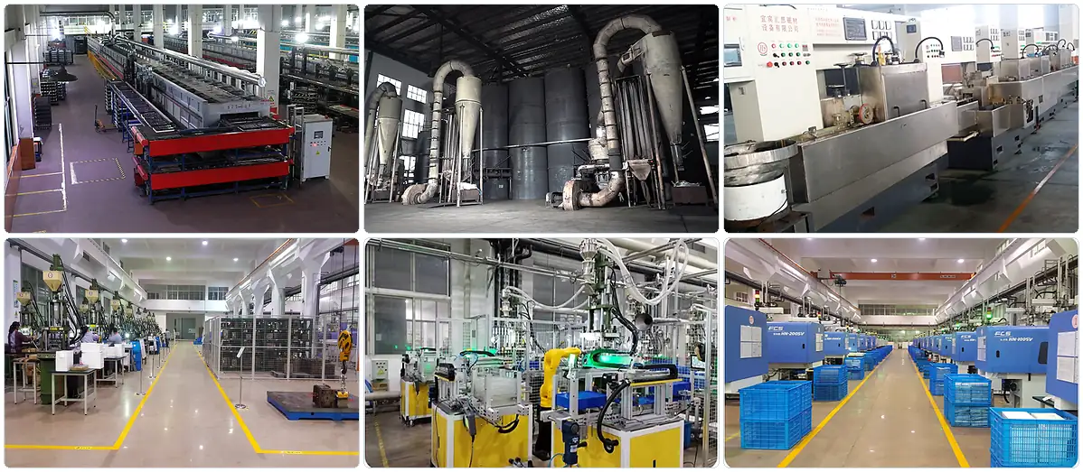
Project route
GX translates initial magnetic performance requirements into a fully engineered production route — covering material, forming, tooling, magnetization and quality control — all validated before volume production commitment.
Define application operating conditions, working air gap, flux / waveform target, temperature range and assembly interface scope.
Evaluate bonded ferrite and NdFeB systems with PA12 / PA6 / PPS binders, calibrated to performance, temperature and cost targets.
Specify injection molding (0.3 mm thin walls, insert overmolding) or compression bonding (higher-flux rings/discs) by geometry, tolerance and volume.
Coordinate gating design, insert overmolding, datum logic, shrinkage compensation and inspection accessibility.
Complete FAI dimensional check, magnetic scanning and mechanical validation, with Cpk ≥ 1.33 for all critical features.
Formal release with approved drawings, samples and inspection plan; SPC monitoring ensures consistent volume supply.
Verification
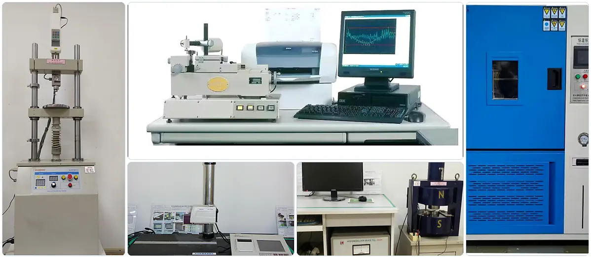
Our IATF 16949-aligned control plan is built around approved drawing revisions, covering dimensional, magnetic, mechanical and aesthetic criteria tailored to each project.
| Inspection item | Control approach | Why the buyer needs it |
|---|---|---|
| Formed dimensions | Critical dimensions & datums inspected via calibrated gauges; tolerance capability verified to Cpk ≥ 1.33 for features as tight as ±0.03 mm | Guarantees consistent fit, alignment and positioning within customer mating assemblies |
| Interface relationship | Concentricity, radial runout, retention torque and pull-out force tested per project specification | Ensures stable rotational performance, secure mechanical retention and precise assembly location |
| Magnetic result | Flux density, 2–64 pole pattern (±1° accuracy) and output waveform verified at specified air gap | Validates compliance with the approved magnetic design and functional performance targets |
| Polarity | Pole direction and sequence verified against approved orientation drawings with 100% magnetic check | Eliminates installation errors and ensures correct motor commutation and sensor output |
| Appearance | Flash, surface finish, burr and edge break assessed against project-specific cosmetic standards | Minimizes assembly interference risk and avoids cosmetic acceptance discrepancies |
Application fit
Application performance is determined by geometry, magnetic pole design, operating environment, assembly interface and consistent production repeatability.
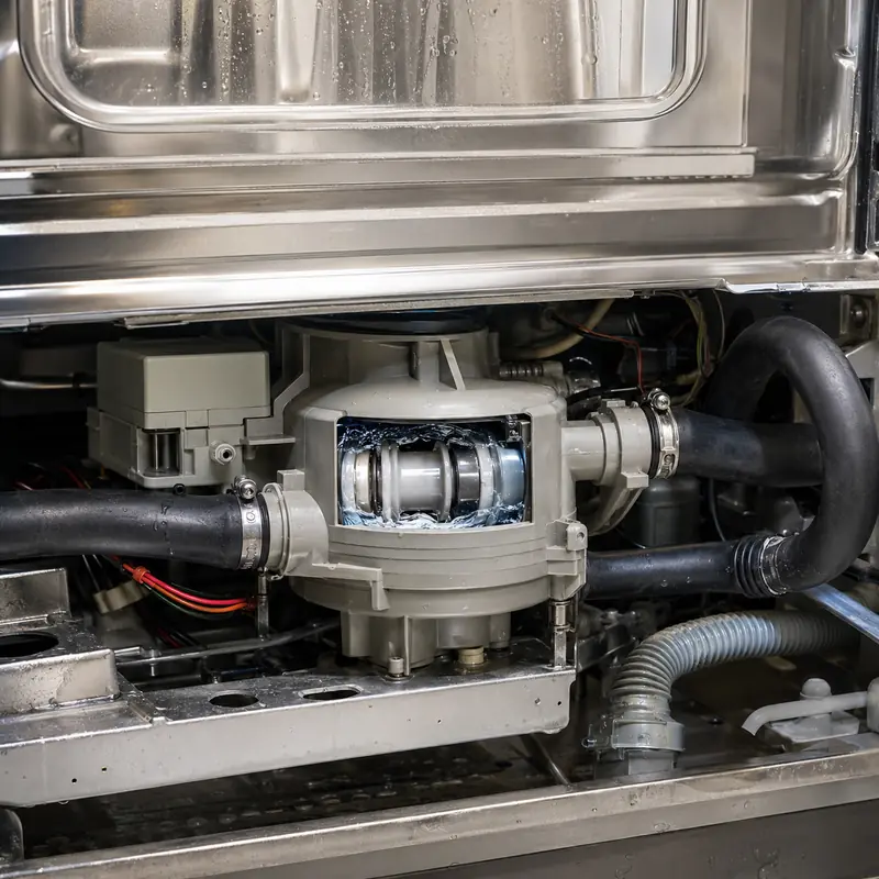
For custom injection molded magnetic rotors, define wall thickness (down to 0.3 mm), ribs, inserts, hub/shaft overmold interface, 2–64 pole map (±1° accuracy), flux/torque targets, and operating temperature (up to 150 °C with PPS). Tooling-sample approval includes dimensional FAI and application-specific magnetic performance validation.

Integrate custom injection magnets with insert, hub, shaft or overmold interfaces for automotive auxiliary drives. Review molded geometry, pole layout, flux output, temperature range (–40 °C to 150 °C), chemical resistance and vibration load. The release package follows IATF 16949, with sample dimensions, magnetic validation and drawing revision control.

For precision sensors and encoders, molded wall geometry, inserts and datum features directly govern assembly fit and signal integrity. Define overmold interface, 2–64 pole pattern (±1° placement accuracy), target flux/waveform, and operating temperature range. Full dimensional and magnetic validation of tooling samples is required prior to serial production.

Develop custom injection magnet assemblies from initial geometry, inserts, hub/shaft overmold, pole map and flux targets, through to environmental and mechanical load qualification. Verify tooling-sample dimensions and application magnetic performance against final released drawings, with full batch traceability for OEM supply.
Quality-system support
GX Magnet operates an IATF 16949‑certified quality management system, governing drawing revision control, sample qualification and project‑tailored inspection planning across the full product lifecycle.
All critical geometry, mating interfaces, pole layouts and appearance criteria follow the latest approved drawing revision. Formal engineering change control ensures uniform specifications across all production batches.
Full First Article Inspection (FAI) documents dimensional results, magnetic performance and functional checks before serial production. Critical feature capability Cpk ≥ 1.33 is recorded as the official release baseline.
Inspection scope, sampling plans and acceptance criteria are defined and agreed at the quotation and release stage. In‑process SPC monitoring delivers consistent, traceable quality in volume production.
Project‑specific quality certificates, inspection records and magnetic performance reports are available upon request during sample approval or technical review, based on approved drawings and mutually agreed acceptance criteria.
Buyer communication
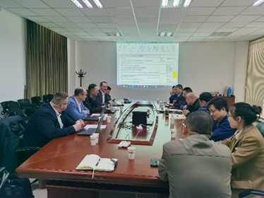
GX Magnet partners with OEM engineering and sourcing teams through technical consultations and industry events, bringing deep expertise in bonded magnetic materials, precision molded components and motor rotor integration. Bring your drawing, mating‑part specifications or magnetic performance requirements — our upfront discussion clarifies material routes, assembly interface risks and RFQ details before formal engineering review begins.
Evaluate part geometries, insert overmolding designs and material form options upfront to align on the optimal quotation and manufacturing route before formal project kickoff.
Deep‑dive review of pole layout accuracy, assembly interface compatibility, operating environment limits and full validation requirements, with actionable DFM feedback to optimize manufacturability and cost.
Structure your qualification process with clear milestones for drawing review, sample approval, inspection documentation and ongoing production communication, fully backed by our IATF 16949 quality system.
Engineering and sourcing FAQ
Practical FAQs for custom injection magnet projects, covering material selection, molded geometry, insert or overmolded features, magnetization requirements, inspection methods and sample-to-production release.
The main differences are the material route, achievable geometry, magnetic output and assembly method. Compare them in the actual magnetic circuit and operating condition; the product name alone is not enough to select the part.
Start with magnetic powder, binder system and isotropic or anisotropic compound. Then check the required magnetic output, geometry, temperature and commercial volume before fixing a grade in the drawing.
Control the dimensions that set fit, air gap or working position. For this product, review molded geometry, inserts, tolerances, magnetization pattern and assembly interface; avoid applying a tight general tolerance to non-functional surfaces without a measurement reason.
Specify the magnetization axis or pole pattern, pole count where applicable, and the acceptance method. A field value must also state the measurement location, fixture or air gap so supplier and buyer evaluate the same condition.
Temperature capability depends on material grade, geometry, magnetizing state and the magnetic circuit. Provide temperature, chemicals, mechanical load and magnetic circuit; GX can then review demagnetization risk and whether the proposed material route fits the duty.
Use an agreed method tied to the application: material-property testing, surface field at a defined position, flux, pull force, pole pattern or waveform. The released drawing and acceptance plan should state the instrument, fixture and limits.
Send the drawing or 3D model, material or magnetic target, molded geometry, inserts, tolerances, magnetization pattern and assembly interface, temperature, chemicals, mechanical load and magnetic circuit, expected quantity and acceptance method. State whether tooling, inserts, assembly or magnetization is included in the requested supply scope.
Agree the drawing revision, tooling state, critical dimensions and magnetic test method before sample release. Approval should identify the sample record and any deviations; recurring orders then follow the released specification, quotation and control plan.
Request for quotation
Include the application, 2D/3D drawing, magnetic target and test condition, operating environment, mating interfaces, sample quantity and annual demand.