

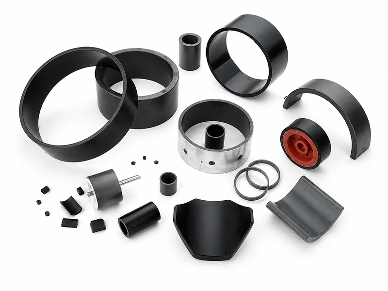
Ring Fit and Working Gap
OD, ID, length, wall section and concentricity are reviewed against the rotor, housing or sensor interface. The working air gap and drawing datums are defined before magnetic output is accepted.
INJECTION-MOLDED NdFeB · MULTIPOLE RINGS
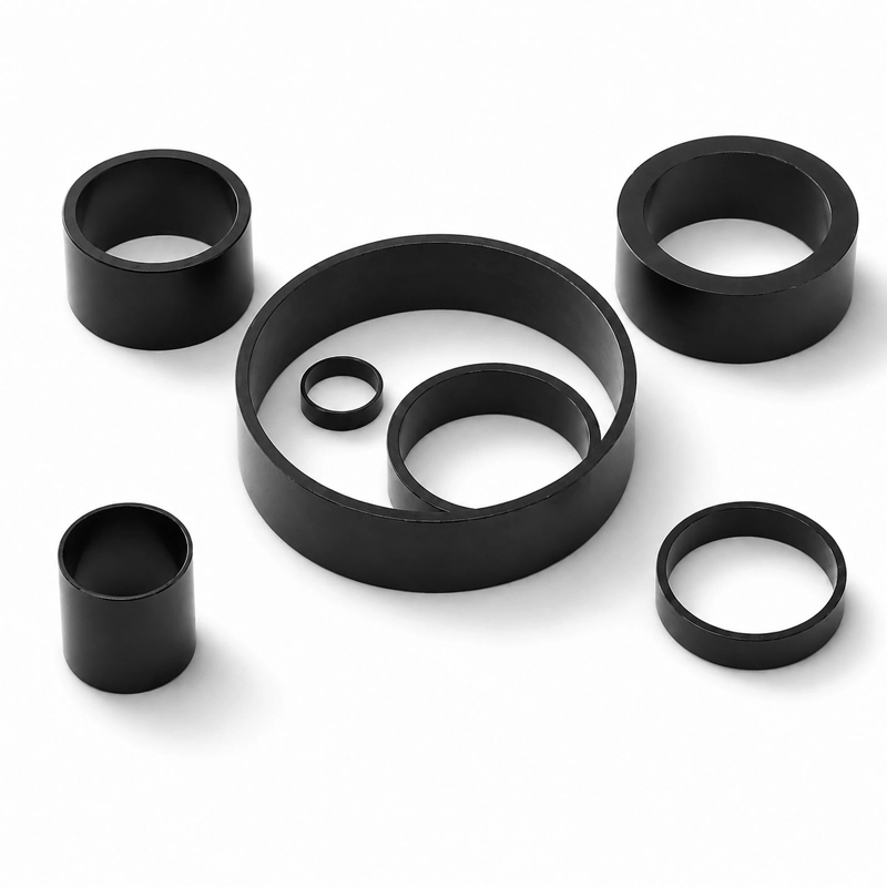
GX manufactures bonded NdFeB ring magnets for position sensing, speed detection, motor feedback and compact rotor programs. Ring geometry, mounting features, pole patterns and magnetic acceptance criteria are defined by the released drawing and approved sample.









FOR A FASTER QUOTATION
Send a marked 2D drawing and available 3D model together with the required magnetic signal, operating conditions and estimated demand. This allows GX to review manufacturability, magnetizing-tool requirements, inspection scope and tooling cost before quotation.
Why choose us for your project
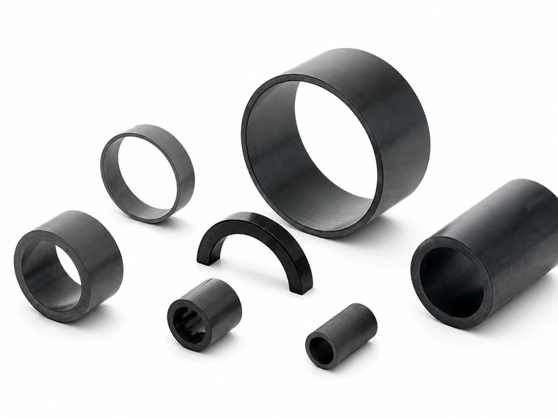
Automotive sensor rings must hold their position while producing a repeatable magnetic signal at the specified air gap. GX reviews OD, ID, wall section, concentricity, pole layout and magnetization together before tooling and magnetizing-fixture release.

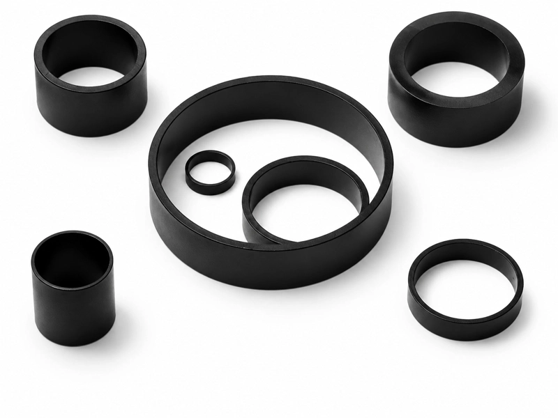
OD, ID, length, wall section and concentricity are reviewed against the rotor, housing or sensor interface. The working air gap and drawing datums are defined before magnetic output is accepted.
Radial or planar magnetization is selected from the sensing function. Project examples include an 8 mm OD, 12-pole radial magnet and a 64-pole planar-magnetized ring, with pole sequence and waveform reviewed as finished-part requirements.
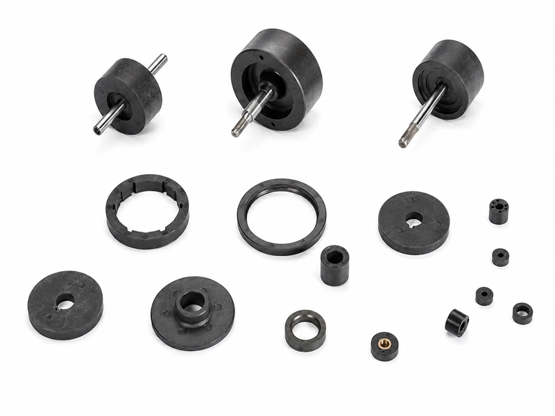
For insert-integrated rings, GX reviews the hub, shaft or sleeve position together with concentricity, runout and retention requirements. This reduces signal variation caused by installation offset or ring movement.
Why choose us for your project
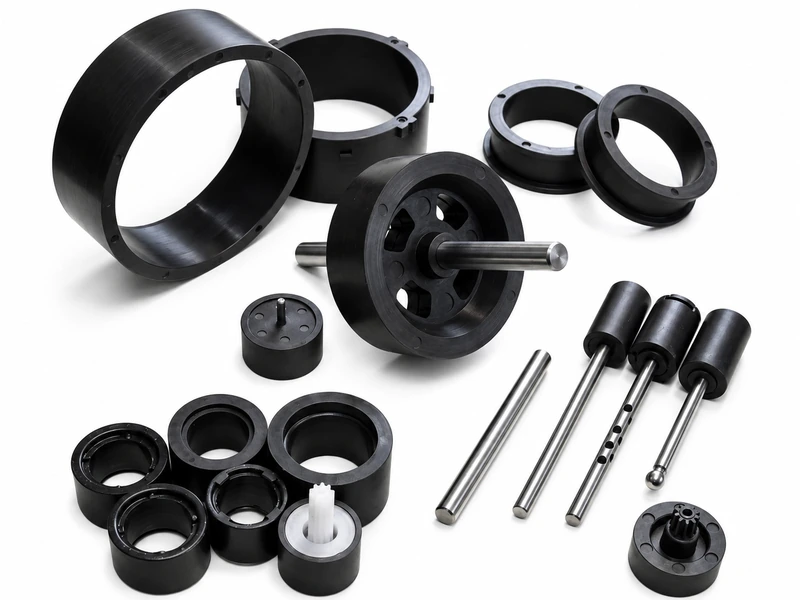
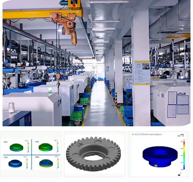
For bonded NdFeB rings with internal keys, locating features, gears or molded interfaces, GX reviews molding flow and predicted deformation before tooling release. The process is designed around the formed ring, its functional interface and the required magnetic output—not the nominal shape alone.
Mold-flow analysis evaluates filling and gate conditions. X-, Y- and Z-direction deformation, together with total deformation, are reviewed to identify shrinkage-related fit or runout risk before steel is cut.
The magnetic body is molded first, followed by the gear, base, locating feature or surrounding functional structure. This reduces separate press-fitting and adhesive-bonding steps where the component design permits.
Tooling datums, parting lines and locating features are reviewed with the shaft, hub, sleeve or mating component. Critical dimensions and interface position are then verified on the formed part during sample approval.
Why choose us for your project
Catalog material data does not release a sensor ring. GX links the approved drawing to finished-part dimensions, magnetic output and the agreed measurement conditions, so sample approval and recurring lot release use the same acceptance basis.
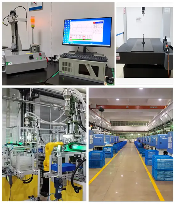
OD, ID, length, critical locating features, insert position, concentricity and runout are inspected against the released drawing and agreed measurement method.
Polarity, pole count, pole sequence, pole position, flux, surface field or waveform are checked at the specified air gap, position, fixture and temperature. Where signal output is defined as critical, full-circumference flux inspection can be included in the agreed plan.
The approved drawing, material batch, mold, magnetizing fixture and inspection record establish the release trail for recurring production. FAI, control-plan, SPC/Cpk records and PPAP submissions are provided when required by the program.
Product and supply scope
A bonded neodymium ring magnet is a net‑shape magnetic component compounded from NdFeB magnetic powder and polymer binder.
GX assesses every project against customer drawings and real‑world application conditions. The manufacturing route — injection molding or compression bonding — is not determined solely by part geometry. Process selection is finalized after evaluating part geometry, magnetic targets, assembly approach, working environment and order volume.
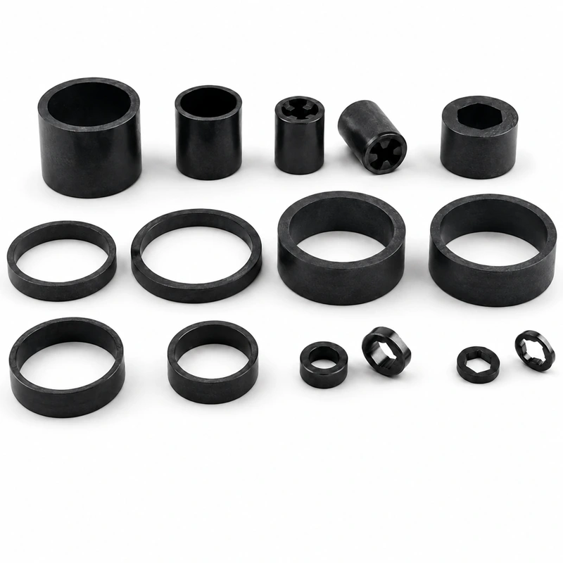
Drawing variables
Geometry, magnetic performance, forming process and mating assembly are evaluated as an integrated component system.
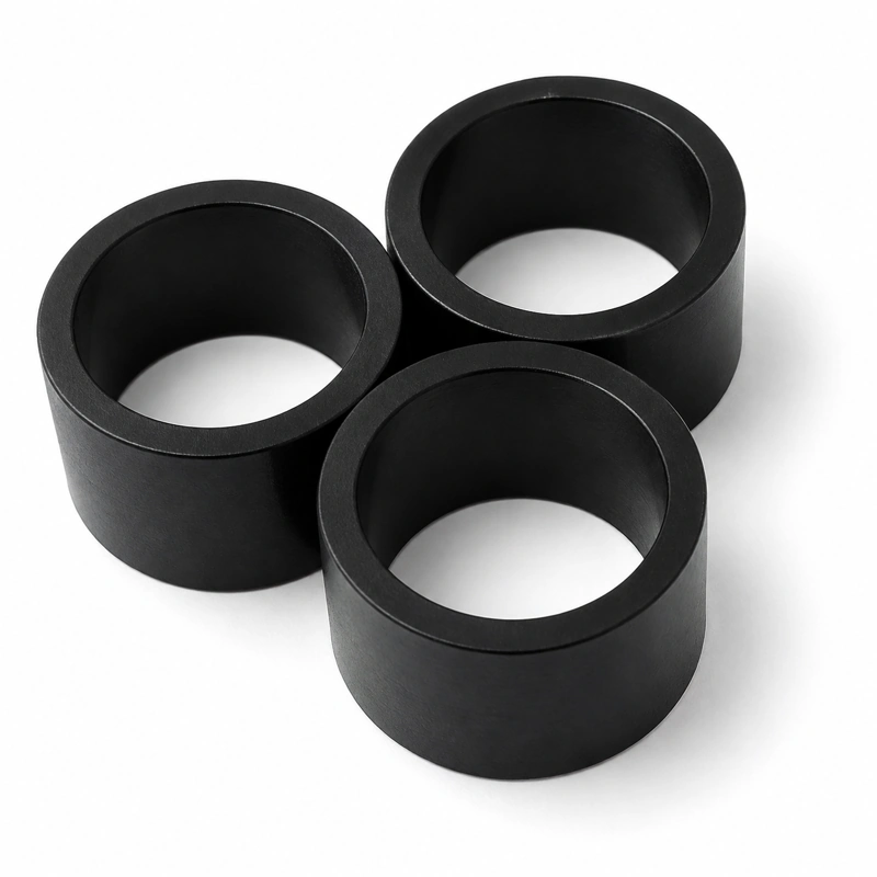
Technical parameters for quotation
This table sorts customer‑provided engineering inputs in logical sequence. Reference ranges serve for preliminary evaluation. Final technical values take effect as formal supply commitments upon alignment within released drawings, approved specifications, quotation terms and acceptance plan.
| Parameter group | Project-specific review basis | Release basis |
|---|---|---|
| Material / route | Bonded Neodymium compound; injection‑molded or compression‑bonded route selected with defined magnetic grade and binder system | Material grade and forming route locked within released drawing, approved specification and acceptance plan. |
| Geometry and tolerances | OD, ID, axial length, concentricity, run‑out, wall thickness and critical datums | Dimensional limits, tolerances and datums take effect via released drawing and formal acceptance plan. |
| Magnetic or functional requirement | Composite material targets, pole count, field distribution, flux and waveform performance at agreed working air‑gap | Magnetic targets, pole pattern and air‑gap waveform criteria finalized within approved specification and acceptance plan. |
| Mechanical / assembly interface | Axial‑radial or multipole layout; mating conditions for hub, shaft and adhesive, together with mechanical retention requirements | Mating interface, torque and retention requirements formalized in released drawing and acceptance plan. |
| Operating environment | Operating temperature, rotating speed, corrosive media, thermal cycling and demagnetizing opposing‑field conditions | Validated operating‑condition limits documented within approved project specification. |
| Inspection and acceptance | Dimensional inspection, polarity check, pole position accuracy, field mapping and waveform documentation | Test items, sampling rules and pass‑fail thresholds defined in formal acceptance plan and specification. |
| Supply boundary | Bonded NdFeB ring as standard deliverable. Rotor integration scope applies under separate defined documentation | Deliverable scope is fully defined within released drawing and project‑specific acceptance documentation. |
Project route
Project workflow covering geometry validation, process selection, tooling definition, magnetization qualification before serial production launch.
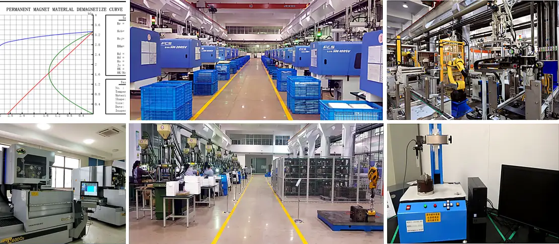
Evaluate part geometry, working air‑gap, magnetization direction, operating environment and assembly interface against end‑use requirements.
Select injection‑molded or compression‑bonded process based on magnetic targets, wall thickness complexity and annual production volume.
Confirm parting line, shrinkage compensation, measurement datums, edge features and inspection accessibility for tool construction.
Complete mass production forming plus required secondary operations such as cutting, grinding and dimension sorting per drawing.
Prototype magnetization, verify pole layout, dimensional accuracy and air‑gap magnetic waveform against agreed acceptance criteria.
Serial production runs follow released drawing, approved sample and formal inspection control plan for repeat orders.
Verification
Inspection control plan executes per released drawing, covering magnetic performance, mechanical geometry and visual appearance defined in project acceptance requirements.
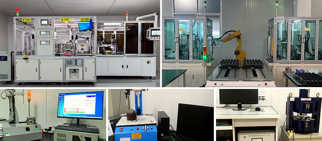
| Inspection item | Control approach | Why the buyer needs it |
|---|---|---|
| Formed dimensions | Measure critical dimensions and functional datums using calibrated gauges and coordinate‑measurement equipment. | Guarantees precise fit and positional accuracy within rotor assembly hardware. |
| Interface relationship | Carry out testing for positional tolerance, run‑out, mechanical retention and torque‑holding performance. | Delivers stable rotary running performance and consistent clamping strength under operating load. |
| Magnetic result | Test magnetic property output, pole layout and functional waveform under defined working air‑gap condition. | Validates real‑world magnetic response matches the original magnetic design target. |
| Polarity | Verify magnetization direction and pole‑sequence against approved orientation drawings and scan‑tool data. | Eliminates assembly mis‑orientation and avoids sensor commutation malfunction. |
| Appearance | Evaluate burrs, flash, surface defect and edge profile against agreed acceptance criteria. | Minimizes assembly interference and lowers post‑delivery quality dispute risks. |
Application fit
Application suitability is determined by part geometry, multipole layout, operating‑condition limits, assembly interface and mass‑production repeatability requirements.

Specify ring OD, ID, length, concentricity, run‑out, pole count and hub‑shaft‑sleeve mating. Define pole pattern, flux waveform, temperature, speed and thermal cycling. Sample approval validates dimension, run‑out and multipole waveform before mass production.

Define hub, shaft or sleeve mounting interfaces. Lock OD, ID, length, concentricity, pole parameters, flux waveform and environmental limits. Project release covers dimension, run‑out, multipole waveform and controlled drawing revision.
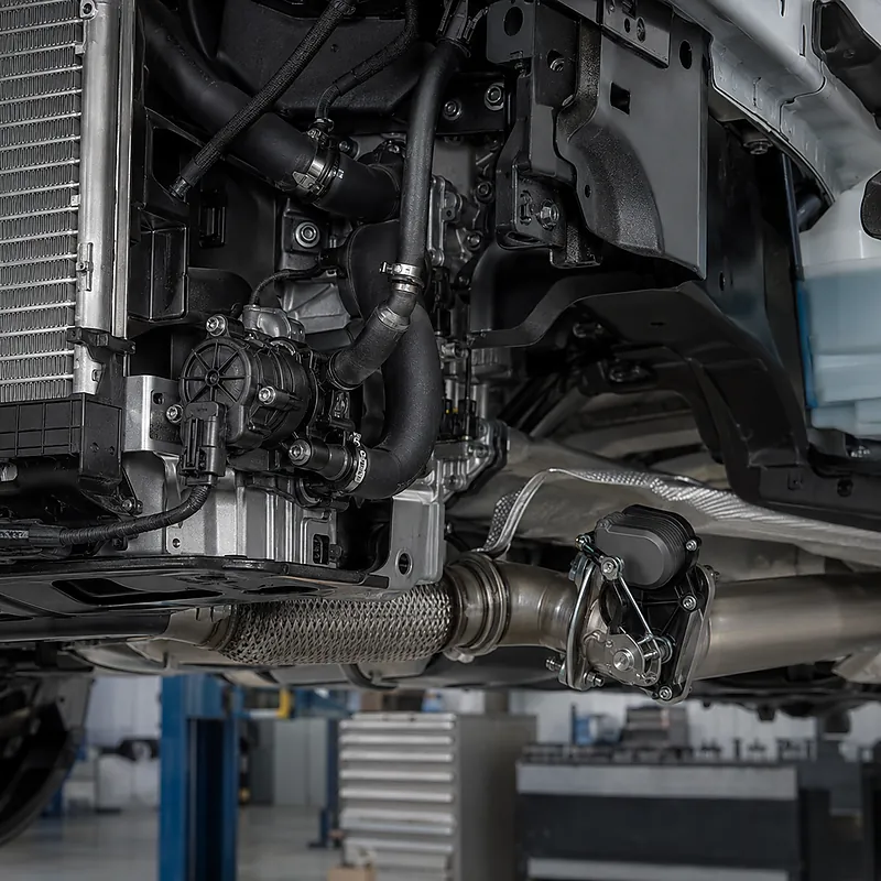
Ring OD, ID, concentricity, run‑out and pole count directly influence assembly fit and performance. Confirm shaft‑hub interface, pole parameters, flux waveform and working conditions. Verify dimension and multipole waveform prior to serial orders.
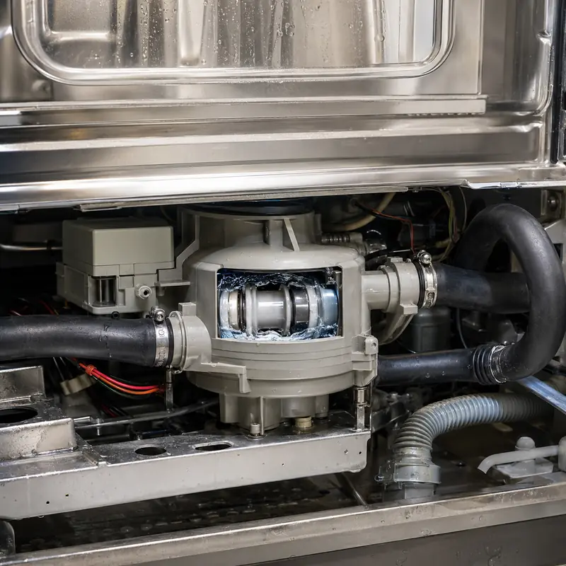
Finalize ring geometry, pole count and hub‑shaft‑sleeve interface requirements. Document pole position, flux waveform and environmental operating limits. Inspect dimension, run‑out and multipole waveform against released drawing.
Quality-system support
GX Magnet operates under IATF 16949 quality system to manage drawing revision control, sample validation and project‑tailored inspection plans.
Critical dimensions, mating interfaces, multipole layout and visual requirements are strictly governed by released drawing revision.
Prototype dimensional measurement, magnetic waveform and functional test data are fully documented prior to mass‑production release.
Inspection items, sampling frequency and acceptance thresholds are finalized at quotation stage for serial production batches.
Project‑specific COC documents, full inspection logs and magnetic test datasets are available upon request, aligned with released drawing and agreed acceptance criteria.
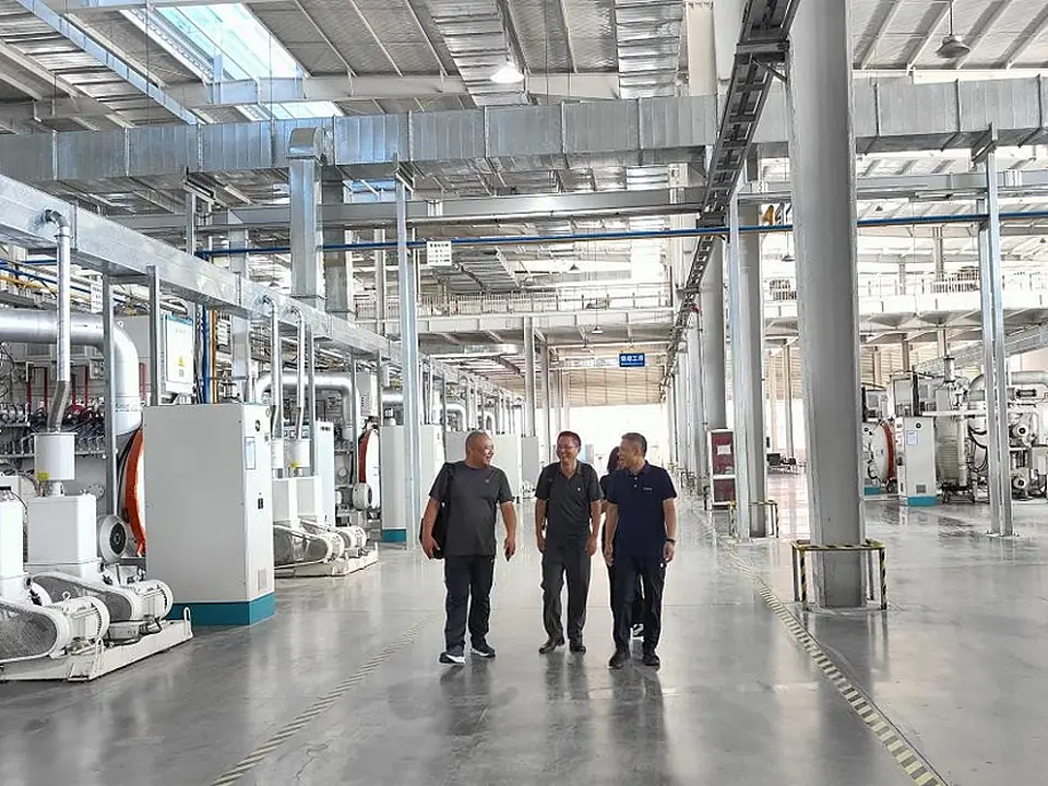
Buyer communication
GX Magnet engages OEM engineers and sourcing teams via industrial exhibitions, showcasing molded magnetic components and motor‑part manufacturing capabilities. Share your drawings, mating‑part data or magnetic‑function requirements. We clarify material selection, interface risks and RFQ prerequisites prior to formal engineering assessment.
Evaluate part geometry, insert structures and product configurations to define feasible quotation paths.
Jointly assess pole patterns, assembly interfaces, operating‑condition limits and project validation requirements.
Align drawing review workflow, sample‑approval process, inspection documentation and ongoing project communication.
Engineering and sourcing FAQ
Use these questions to define the finished ring, required magnetic signal, measurement conditions and production-release criteria before tooling or sample approval.
The main differences are the material route, achievable geometry, magnetic output and assembly method. Compare them in the actual magnetic circuit and operating condition; the product name alone is not enough to select the part.
Start with NdFeB compound, binder, orientation and pole-count requirement. Then check the required magnetic output, geometry, temperature and commercial volume before fixing a grade in the drawing.
Control the dimensions that set fit, air gap or working position. For this product, review outer and inner diameter, length, concentricity, runout, pole pattern and waveform; avoid applying a tight general tolerance to non-functional surfaces without a measurement reason.
Specify the magnetization axis or pole pattern, pole count where applicable, and the acceptance method. A field value must also state the measurement location, fixture or air gap so supplier and buyer evaluate the same condition.
Temperature capability depends on material grade, geometry, magnetizing state and the magnetic circuit. Provide temperature, rotational speed, working air gap and corrosion medium; GX can then review demagnetization risk and whether the proposed material route fits the duty.
Use an agreed method tied to the application: material-property testing, surface field at a defined position, flux, pull force, pole pattern or waveform. The released drawing and acceptance plan should state the instrument, fixture and limits.
Send the drawing or 3D model, material or magnetic target, outer and inner diameter, length, concentricity, runout, pole pattern and waveform, temperature, rotational speed, working air gap and corrosion medium, expected quantity and acceptance method. State whether tooling, inserts, assembly or magnetization is included in the requested supply scope.
Agree the drawing revision, tooling state, critical dimensions and magnetic test method before sample release. Approval should identify the sample record and any deviations; recurring orders then follow the released specification, quotation and control plan.
Request for quotation
Include the application, 2D/3D drawing, magnetic target and test condition, operating environment, mating interfaces, sample quantity and annual demand.