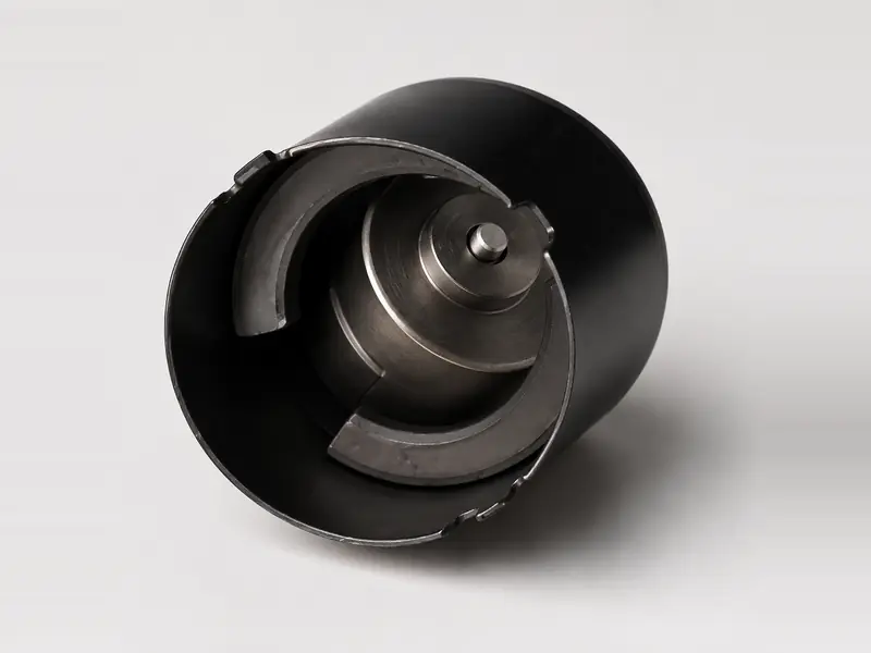








Two-Pole Layout
Two opposing ferrite segments are reviewed for arc angle, working face, air gap and magnetic orientation.
Motor Stator · Permanent Magnet Stator
GX Magnet supplies drawing-defined permanent magnet stators using ferrite magnet segments assembled inside an approved steel yoke or motor housing. This page covers the fixed magnetic field assembly and does not imply copper winding, a bus bar or a winding temperature sensor.

Drawing variables
Pole count, magnet arc, housing geometry, retention and mating-rotor conditions must be evaluated as one component system.
| Parameter | Specification / Review Basis |
|---|---|
| Stator Structure | Ferrite arc magnet segments assembled inside a drawing-defined steel yoke or motor housing |
| Magnet Material | Hard ferrite / ceramic ferrite according to the approved project specification |
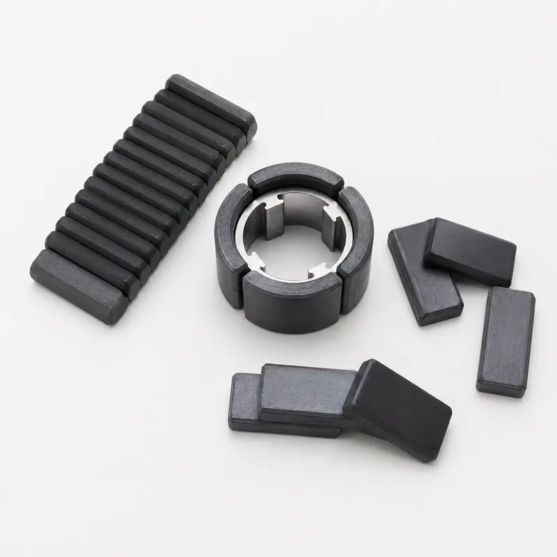
| Pole Configuration | Two-pole, four-pole or project-defined multi-segment arrangement |
| Magnetization | Direction, pole sequence and installed orientation confirmed from the pole map and drawing |
| Key Interfaces | Magnet arc, housing inner diameter, rotor diameter, working air gap, datums and retention method |
| Operating Conditions | Temperature, moisture, chemicals, vibration and validation cycle reviewed by application |
| Customization Basis | 2D/3D drawings, mating-rotor information, sample quantity and annual demand |
| Acceptance Basis | Approved drawing, sample and agreed dimensional, magnetic and assembly inspection method |
Project screening
A usable review starts with the fixed magnet structure, mating rotor, air gap and housing interface—not only the product name.
Product relationship
Each motor-stator page carries a distinct sourcing intent. Select the route that matches the drawing and assembly scope.
Product and supply scope
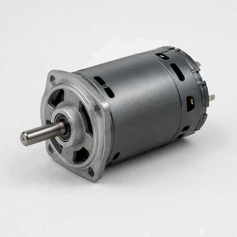
In the supply scope of this page, a permanent magnet stator is the stationary magnetic-field assembly used in PMDC and related motor structures. Ferrite arc magnets are positioned and retained inside a steel yoke or motor housing around the rotor working gap.
GX evaluates the magnet geometry, pole layout, steel interface, retention method, air-gap relationship and inspection plan from the customer drawing. Copper winding, a stator bus bar and a winding temperature sensor are outside this page’s stated supply scope.

Project route
GX connects ferrite magnet selection, housing interface, assembly planning, magnetization verification and recurring inspection to one approved project route.

Motor type, drawing, rotor interface, environment, tolerances and demand are checked together.
Pole layout, ferrite arc geometry, steel yoke and retention concept are compared with the application.
Datums, critical dimensions, assembly access and measurement points are confirmed.
Confirmed ferrite segments and steel components are prepared under drawing control.
Pole position, dimensions, retention and magnetic result are checked before approval.
Approved drawings, samples and inspection criteria govern recurring batches.
Verification
The control plan follows the approved drawing and the project’s agreed dimensional, magnetic, mechanical and appearance requirements.

| Inspection item | Control approach | Why the buyer needs it |
|---|---|---|
| Housing and magnet dimensions | Critical dimensions and datums checked with agreed gauges or measurement methods | Controls fit and working-gap consistency |
| Concentricity / runout | Rotor-related datum and inner working surface evaluated where specified | Supports stable air gap and motor operation |
| Magnetic result | Agreed property, pole pattern or functional check under defined conditions | Connects the stator to the approved motor design |
| Polarity and position | Direction, pole sequence and circumferential position verified to drawing | Prevents incorrect assembly or rotation behavior |
| Retention / appearance | Joint, edge, contamination and appearance criteria evaluated to the agreed standard | Reduces assembly interference and acceptance disputes |
Application fit
Application fit depends on pole layout, housing interface, air gap, operating environment and the required production repeatability.

Two-pole structures are reviewed with rotor diameter, working gap, torque target and housing interface.

Pole position, moisture exposure, retention and the mating rotor are evaluated together.

Assembly repeatability, noise-related constraints and dimensional acceptance follow the motor drawing.

Special housings, pole layouts and interfaces are quoted only after drawing and project review.
Quality-system support
GX Magnet applies its IATF 16949 quality system to drawing revision, sample approval and project-defined inspection planning.
Magnet geometry, housing datums, pole layout, retention and appearance criteria follow the approved drawing revision.
Prototype dimensions and agreed magnetic, fit or functional checks are recorded before recurring production.
Inspection scope and sampling expectations are aligned before quotation and release.
Project-specific certificates, inspection records and magnetic performance data can be provided during sample approval or project review, based on the approved drawing and agreed acceptance criteria.

Buyer communication
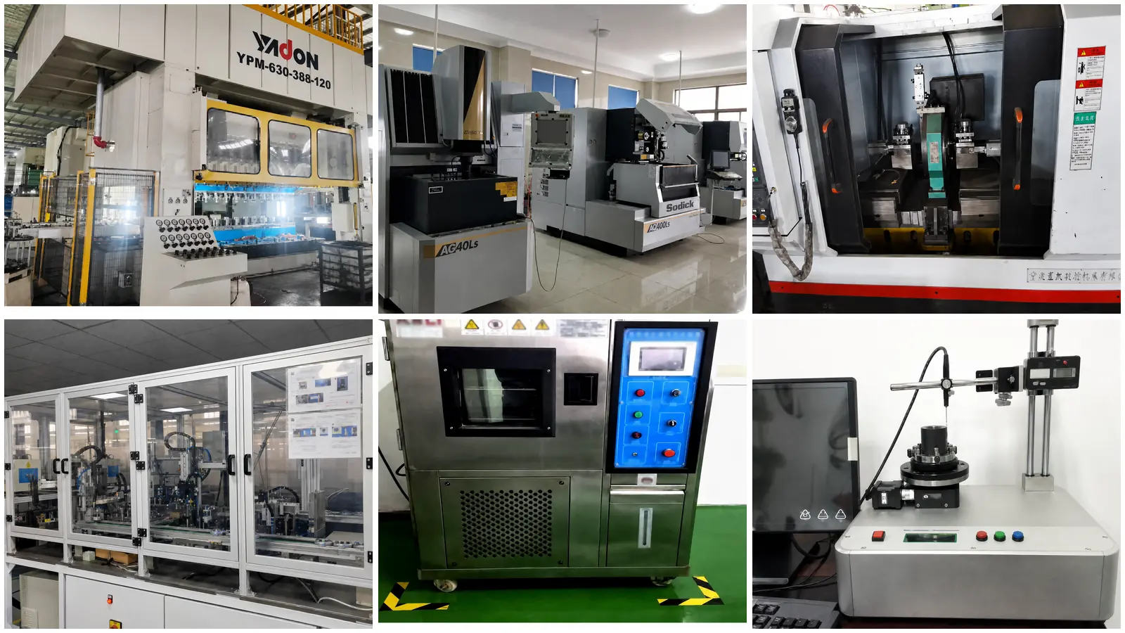
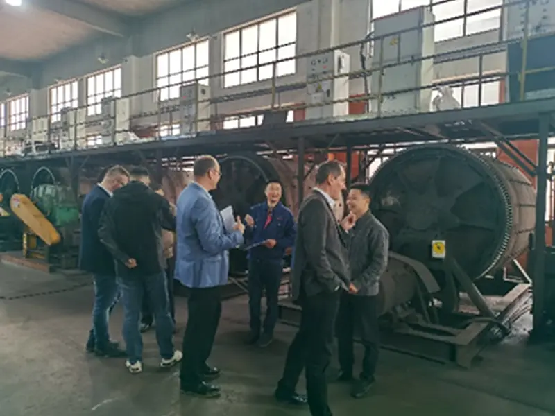
GX Magnet uses industrial exhibitions to present ferrite materials, magnetic assemblies and motor-component capabilities to OEM buyers, engineers and sourcing teams.
Bring the stator drawing, mating-rotor information or a magnetic-function question. The discussion can identify the supply boundary, interface risks and RFQ information needed before formal engineering review.
Compare pole layouts, housings and stator forms before choosing the quotation route.
Review air gap, interfaces, environment and validation expectations.
Plan drawing review, sample approval, inspection evidence and recurring communication.
GX Magnet
GX Magnet combines ferrite-material experience, magnetic-component capability and motor-stator project support for automotive, appliance, pump, HVAC and industrial applications.
Ferrite magnet material, pole layout, steel interface and retention are reviewed against the application.
Tooling, interfaces, samples and inspection criteria are controlled from approved revisions.
Engineering and sourcing teams receive a clear RFQ input list and project-specific supply boundary.
FAQ
These answers define the first engineering review without applying universal values to every custom stator.
The stated scope is ferrite magnet segments assembled with a drawing-defined steel yoke or housing. The final scope is confirmed from the customer drawing and approved sample.
No. This page covers a fixed ferrite-magnet stator structure and does not imply copper winding, a stator bus bar or a winding temperature sensor.
Yes. Two-pole, four-pole and other segment arrangements can be evaluated from the pole map, magnet drawing, steel housing, mating rotor and acceptance method.
Provide 2D/3D drawings, motor type, pole layout, mating rotor and air gap, operating environment, critical dimensions, sample quantity and annual demand.
Request for quotation
Include the motor type, 2D/3D drawings, pole layout, rotor and housing interfaces, operating environment, sample quantity and annual demand.