
Material and Heat Treatment
Ø2–50 mm · 20–60 HRC · case depth 0.2–1.5 mm — steel grade, heat-treatment condition and corrosion protection are specified on the drawing.
Motor Rotor · Precision Shaft Interfaces
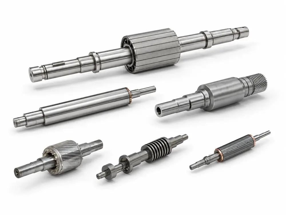
GX Magnet supplies rotor shafts and shaft-integrated rotor subassemblies manufactured to customer drawings. Material condition, bearing seats, rotor fits, shoulders and torque-transfer features are controlled from a common datum scheme to support accurate assembly and stable rotation.









RFQ essentials
Diameter and length are not enough. A reliable quotation also requires the datum structure, mating fits, material condition, operating loads and speed.
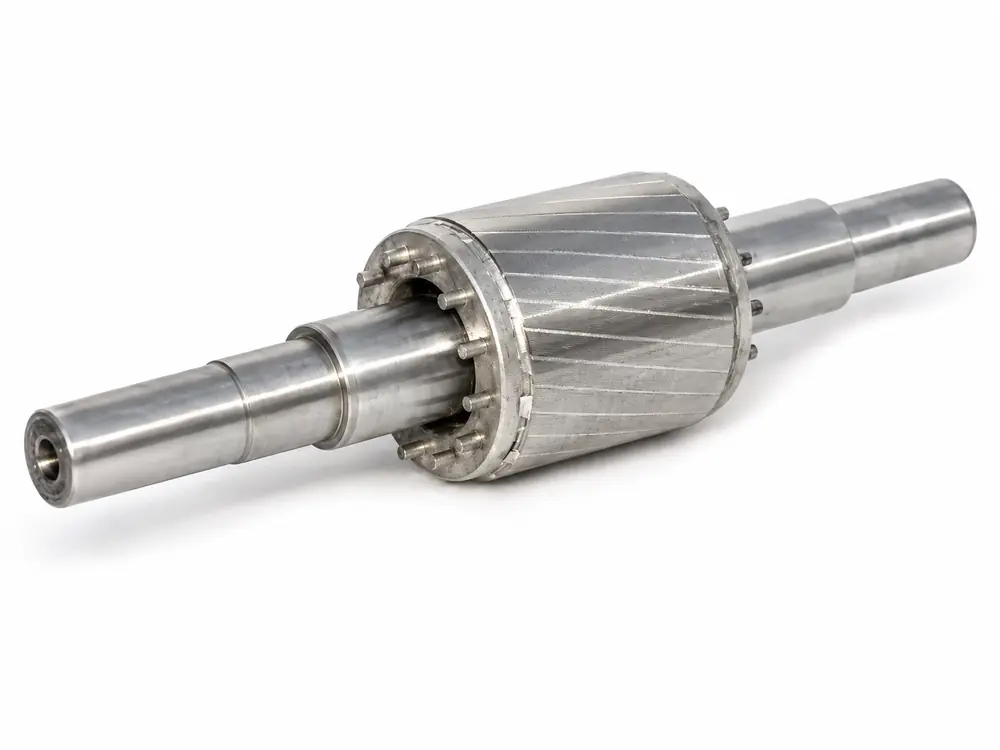
GX supplies rotor shaft assemblies using sintered ferrite, bonded ferrite and NdFeB magnets. Available constructions include press-fit, injection-molded, SPM, IPM, segmented-magnet, overmolded and custom multipole designs manufactured to customer drawings.


Construction:


Construction:
Explore our comprehensive range of magnetic materials and assembly configurations. Compare costs, magnetic properties, and typical applications to find the optimal solution for your engineering requirements.
| Category | Material | Cost | Magnetic Properties | Temp. Resistance | Shape Freedom | Typical Applications |
|---|---|---|---|---|---|---|
| Sintered Ferrite Ring Press-fit | Sintered Ferrite | Low | Low | High | Low | Water Pumps, Home Appliances |
| Bonded / Injection Molded Ferrite | Bonded Ferrite | Medium-Low | Low | Medium | High | Small Pumps, Sensors |
| NdFeB Surface Mounted (SPM) | Sintered NdFeB | High | High | Medium | Medium | BLDC Motors, Servos |
| NdFeB Interior (IPM) | Sintered NdFeB | High | High | Medium-High | Low | Automotive Drive, High-Speed Motors |
| Segmented Magnet Splicing | Ferrite / NdFeB | Medium-High | Medium-High | Medium-High | High | Large Motors, Industrial |
| Injection Overmolded | Sintered / Bonded + Plastic | Medium | Medium | Medium | Highest | Pumps, Home Appliances |
| Custom Multi-pole Precision | Various | Custom | Custom | Custom | Highest | Stepper Motors, Servos, Automotive |
Our engineering team can help you select the exact materials and parameters for your project.
Critical design inputs
The material condition, machined features, mating interfaces and rotational tolerances must reference a consistent datum system.
Engineering reference
Final requirements are established from the shaft drawing, material and heat-treatment specification, bearing arrangement, mating rotor, operating loads, speed and inspection method.
| Parameter | Specification / Review Basis |
|---|---|
| Structure / Supply Scope | Shaft Ø2–50 mm · overall length 20–500 mm — supplied as a finished shaft or as a mechanical subassembly with a core, hub or magnetic rotor. Wound armatures and commutators are outside this scope. |
| Material / Condition | 20–60 HRC · case depth 0.2–1.5 mm — carbon steel, alloy steel or stainless steel with the heat treatment and corrosion protection specified on the drawing. |
| Bearing Seats / Fits | IT5–IT7 · roundness 0.003–0.020 mm · cylindricity 0.005–0.030 mm · Ra 0.2–0.8 μm — bearing-seat diameters, shoulders and surface finish are defined for the selected bearings. |
| Rotor Connection | Retention 50–5,000 N · torque 0.1–150 N·m · fits IT6–IT9 — press fit, spline, knurl, keyway, thread or adhesive joint is evaluated against the applied load. |
| Geometric Accuracy | Straightness 0.01–0.10 mm/100 mm · concentricity 0.005–0.050 mm · TIR 0.01–0.10 mm — inspected from the functional bearing-seat datums. |
| Load / Speed | Balancing quality grade G0.4–G6.3 · rated speed ≤20,000 rpm · maximum speed ≤30,000 rpm · overspeed factor 1.2× — radial and axial loads, duty cycle and test conditions are project-specific. |
| Surface / Acceptance | Ra 0.2–3.2 μm · salt-spray exposure 24–240 h, where specified · AQL 0.65–1.5 — coating system, corrosion-test method, sampling plan and acceptance criteria are agreed for each project. |
These figures are indicative review ranges, not universal limits. The approved shaft and mating-component drawings govern the material condition, fits, torque capacity, runout, speed and validation requirements.
Product definition
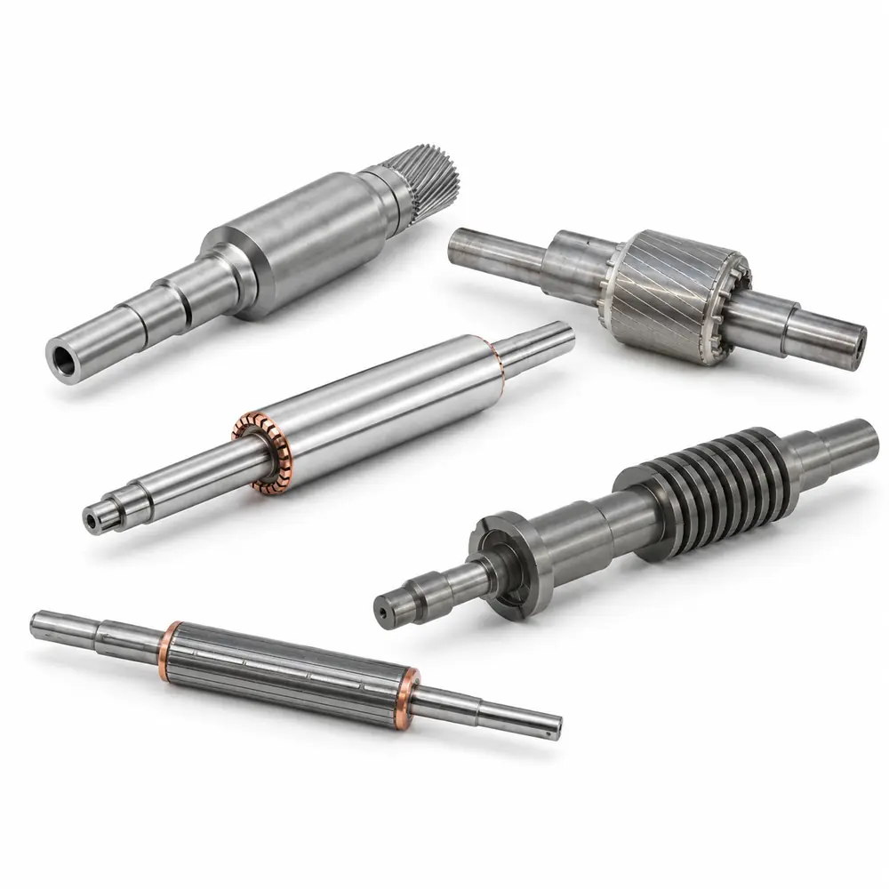
A rotor shaft assembly combines a precision-machined shaft with a rotor core, hub or magnetic rotor to establish the rotating axis and transmit torque within the motor. Bearing seats, rotor-mounting features, shoulders, threads and keyways are defined within a common datum system so that fit, coaxial alignment and total indicated runout (TIR) can be controlled after assembly.
GX Magnet can supply a finished rotor shaft or a drawing-defined shaft-to-rotor subassembly. The approved project scope specifies the material, heat treatment, machining, surface treatment, joining method and final inspection responsibilities.
Manufacturing route
Material preparation, precision machining, heat treatment, finishing, rotor joining and inspection are planned around the same functional datums.

The customer provides drawings for the shaft and mating components. GX reviews them against the specified loads, rotational speed, operating environment and production volume. The review confirms the datum system, tolerance classes, mating methods and design for manufacturability (DFM), with optimization recommendations provided where necessary.
The shaft material—such as Grade 45 carbon steel, 40Cr, 42CrMo or stainless steel—is selected according to the mechanical load and operating speed. The delivery condition, heat-treatment requirements and surface-protection method are then confirmed. Bar stock is cut to length, followed by incoming verification of material grade and hardness.
The outside diameter, end faces and center holes are machined first, while stepped diameters are rough-turned with sufficient allowance for final finishing. Quenching and tempering or localized hardening is performed according to the approved process. Distortion is controlled during heat treatment, and the shaft is straightened afterward to establish stable datums for precision machining.
Bearing seats, rotor-mounting diameters, shoulders, threads and torque-transfer features—including keyways and splines—are finish-machined from the specified datums. Cylindrical grinding can achieve IT5–IT7 tolerance grades while controlling roundness, cylindricity and a surface roughness of Ra 0.2–0.8 μm.
Black oxide treatment, zinc plating, chromium plating or phosphating is applied as specified. The rotor core or magnet assembly is press-fitted onto the shaft using the defined interference fit, positioned by a key or spline where applicable, and secured using the specified locking method. Axial position, fit integrity and dynamic balance are verified after assembly.
Critical dimensions, geometric tolerances—including coaxiality and total indicated runout (TIR)—hardness and surface condition are inspected either 100% or according to the agreed sampling plan. Following first-article approval, recurring production is controlled against the released drawings, approved sample, material records and inspection plan. An inspection report accompanies each shipment.
Inspection and validation
Inspection relates material condition and machined geometry to bearing fit, rotor alignment, torque transfer and the shaft’s functional axis.

| Inspection item | Control method | Purpose |
|---|---|---|
| Bearing seats | Inspect diameter, roundness, cylindricity, surface roughness and axial position using the specified datum system. Measure coaxiality relative to the functional bearing-journal datums. | Ensures the specified bearing fit and accurate rotational alignment. |
| Straightness / runout | Inspect diameter, roundness, cylindricity, surface roughness and axial position using the specified datum system. Measure coaxiality relative to the functional bearing-journal datums. | Helps limit vibration, operating noise and air-gap variation. |
| Material / hardness | Inspect diameter, roundness, cylindricity, surface roughness and axial position using the specified datum system. Measure coaxiality relative to the functional bearing-journal datums. | Confirms the specified material condition and supports the required strength, wear resistance and fatigue life. |
| Rotor connection | Inspect the interference fit, spline parameters, keyway dimensions and position, thread accuracy, knurling and adhesive-joint features against the approved drawing. Perform pull-off force and static torque tests where required. | Ensures reliable axial retention and consistent torque transmission. |
| Edges / surface protection | Evaluate burr removal, edge breaking, cleanliness and coating coverage against the agreed criteria. Verify corrosion protection by salt spray testing where specified, and inspect the rust-preventive oil film and packaging method. | Ensures reliable axial retention and consistent torque transmission. |
Application requirements
Each application places a different priority on bearing accuracy, torque transmission, corrosion protection, rotational speed and noise.

Low noise, long service life and batch-to-batch consistency are key requirements for appliance motors. Ferrite ring magnets can be integrated with the shaft and dynamically balanced to reduce vibration. Plastic overmolding provides protection against moisture and corrosion, while automated high-volume production supports dimensional consistency and stable costs for million-unit programs.
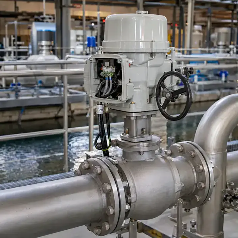
Pump rotors often operate in direct contact with liquids or in humid environments. Sealing-interface accuracy, corrosion resistance and shaft runout therefore affect pump efficiency, sealing reliability and service life. An injection-molded ferrite rotor can be overmolded with the shaft and impeller as a sealed unit. Ceramic or stainless-steel shafts are available for different media. Shaft-journal runout can be controlled to ≤0.02 mm, helping extend mechanical-seal life and reduce leakage risk.
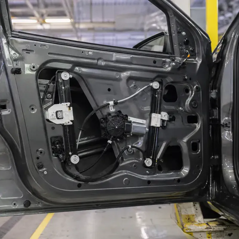
Automotive motors require reliable operation across a wide temperature range of −40°C to 125°C, together with vibration resistance and consistent performance. Surface-mounted or interior NdFeB rotor designs provide high torque and power density in a compact package. Splined or interference-fit shaft connections provide reliable torque transmission without relative movement. Heat treatment establishes the required shaft strength, while surface protection improves corrosion resistance. Quality planning can be aligned with automotive Tier 1 supplier requirements, including project-defined defect targets measured in PPM.
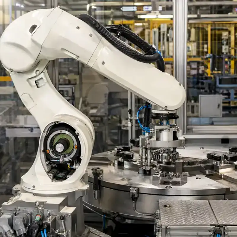
Servo and industrial motors require accurate positioning, high rotational speed and fast dynamic response. Interior permanent-magnet (IPM) rotors provide high torque density and an extended field-weakening range, supporting both high torque at low speed and stable high-speed operation. Precision shaft machining can achieve IT5–IT7 fit tolerances, while dynamic balancing supports stable operation at speeds below 30,000 rpm. Low-inertia rotor designs improve acceleration and response in servo systems.
Engineered for performance. We tailor core magnetic materials, precision machining, and encapsulation processes to meet the exact speed, environmental, and durability demands of your industry.
| Application Scenario | Core Magnetic Material | Speed Range | Key Requirements | GX Advantages |
|---|---|---|---|---|
|
|
Sintered / Injection Ferrite | Low (<5000rpm) | Low noise, low cost, high volume | In-house ferrite production, stable costs; Exclusive supplier for BSH dishwasher pumps. |
|
|
Injection Ferrite | Low-Medium (<8000rpm) | Sealed anti-corrosion, moisture resistant | Integrated injection molding encapsulation, fully sealed; Optional ceramic/stainless steel shafts. |
|
|
Sintered NdFeB | Medium (<15000rpm) | Wide temperature range, high reliability, vibration resistant | NdFeB + Heat treatment + Surface treatment; Manufactured under Automotive Tier 1 quality system. |
|
|
Sintered NdFeB (IPM) | High (<30000rpm) | High precision, high speed, low inertia | IPM internal rotor, IT5-IT7 precision shaft machining, dynamic balance correction integration. |
Our engineers can help you select the optimal material and design for your specific motor application.
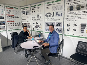
Technical consultation
At industrial exhibitions, GX Magnet discusses magnetic components and rotor subassemblies with OEM engineering and sourcing teams.
A shaft drawing and details of the bearings, mating rotor, load and operating speed allow the team to identify interface risks, clarify the supply boundary and prepare a focused RFQ review.
Compare the released dimensions, datums and mating features with an existing shaft or rotor sample.
Review bearing fits, rotor retention, torque transfer, runout, speed and service conditions.
Define the prototype report, measurement setup, release criteria and records required for repeat orders.
GX Magnet
GX Magnet’s integrated manufacturing resources support drawing-defined magnetic components, rotor structures and mechanical interfaces for automotive, appliance, pump, HVAC and industrial motor applications.
Shaft material, bearing arrangement, rotor connection, load and operating environment are considered as one assembly interface.
The drawing review identifies which parts, assembly operations, inspections and records are included in the quotation.
Engineering and sourcing teams receive a product-specific RFQ checklist and a clear basis for prototype and batch approval.
FAQ
These answers cover the material, fit, datum, joining and inspection details normally settled before prototype approval.
A rotor shaft assembly is a rotating unit built around a precision-machined shaft. Depending on the motor or equipment design, it may include a laminated rotor core, hub, permanent magnets, magnet carrier, retaining sleeve, spacers, end rings or an impeller. The exact supply scope should be defined by the customer drawing and bill of materials.
Common joining methods include interference fitting, press fitting, shrink fitting, splines, keys, adhesives, welding and mechanical locking. The appropriate method depends on transmitted torque, rotational speed, temperature, component materials and serviceability. Joint dimensions, tolerances, surface conditions and assembly sequence should be reviewed together.
The shaft material should be selected according to mechanical strength, fatigue life, wear resistance, corrosion exposure, operating temperature and manufacturing process. The drawing should specify the material grade, delivery condition, heat treatment, hardness range, surface treatment and requirements for bearing seats, seal surfaces and other critical features.
Options include press fits, splines, knurls, keyways, threads, adhesive joints and other drawing-defined features. The review requires the mating-part drawing, specified fit or interference, torque load and assembly method.
Yes, when the approved scope defines the mating rotor, joining process, press force or torque, axial position, runout limits and inspection responsibility.
The manufacturing route accounts for expected distortion, straightening requirements, machining and grinding sequence, and final inspection datums. Hardness and finished dimensions remain subject to the released drawing.
Dynamic balancing is generally required when rotor speed, diameter, length or uneven mass distribution could create excessive vibration, noise or bearing load. Low-speed, narrow rotors may only require static balancing. The drawing should specify the balancing planes, applicable balance grade or residual unbalance limit, and whether balancing is performed before or after final assembly.
Depending on the project, documentation may include material and heat-treatment certificates, first-article or dimensional inspection reports, hardness and surface-finish results, concentricity and TIR records, joint-retention tests and balancing reports. Magnetic rotor assemblies may also require flux, polarity or waveform inspection under an agreed fixture and test condition.
We meticulously control assembly temperatures and physical impacts. Press fits and joining processes are engineered to avoid exceeding the maximum operating temperature of the magnets, ensuring zero loss of magnetic flux or performance.
Rotational speed influences centrifugal stress, critical speed and balancing requirements. Torque determines shaft strength and joint capacity, while temperature affects interference fits, adhesives, coatings and magnetic components. The duty cycle influences fatigue life and thermal loading. These conditions should therefore be evaluated as one operating system rather than as separate parameters.
Request for quotation
Send the shaft and mating-part drawings together with the material condition, functional datums, operating loads, speed and required supply scope.