

Working Field at the Sensor Plane
TMR angle-sensor programs can require an in-plane field of 6–20 mT at the sensor. GX aligns axial or diametric magnetization, disc diameter, thickness and the specified air gap to the target field window.
INJECTION-MOLDED NdFeB · DISC GEOMETRY
GX supplies injection-molded bonded NdFeB disc magnets for OEM assemblies requiring a flat magnetic component with axial or diametric magnetization. Material screening uses Br 0.35–0.65 T, Hcj 600–1,200 kA/m and (BH)max 4–10 MGOe at 20°C; the released specification defines disc diameter, thickness, working face, center configuration, magnetic direction and installation condition.










Before quotation
A complete RFQ package helps GX review the bonded NdFeB compound, disc geometry, magnetization direction, working face and inspection method before sampling or tooling is quoted.
Product relationship
Use this section to move from the bonded neodymium disc page to the nearest material, forming route or geometry category. Choose the related page when the drawing changes from a solid disc to a ring, rotor, insert-molded part or broader injection-molded component.
Why choose us for your project
GX reviews injection-molded bonded NdFeB discs from material data at 20°C through the sensor field, center feature and retention interface. Typical compound screening starts with Br 0.35–0.65 T, Hcj 600–1,200 kA/m and (BH)max 4–10 MGOe, then links these inputs to drawing-defined dimensions and working conditions.
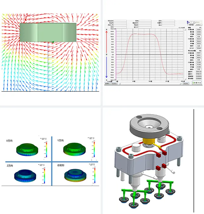
Each disc is reviewed as a functional magnetic component: the working face establishes the magnetic output, while the opposite face and center feature establish the mounting datum and retention path.
TMR angle-sensor programs can require an in-plane field of 6–20 mT at the sensor. GX aligns axial or diametric magnetization, disc diameter, thickness and the specified air gap to the target field window.
OD, thickness, center bore or recess, flatness and axial or radial runout are assigned to released datums. Injection-molded feasibility is reviewed against wall section and a ±0.003 in/in dimensional reference before drawing limits are released.
Material selection combines the 20°C magnetic report with the specified operating temperature, moisture or media exposure, plus adhesive or mechanical retention requirements. The mating face, insert position and inspection method are defined for sample approval.
Why choose us for your project
GX selects injection molding or compression bonding from the disc diameter, thickness, center feature, magnetic target and recurring volume. Injection-molded bonded NdFeB compounds typically use 50–75 vol.% magnetic powder, while compression bonding can support up to 85 vol.% for programs requiring a higher material-energy target.

Magnetic-powder loading, wall section and center geometry are reviewed as one forming condition. Injection molding supports formed recesses, locating features and integrated interfaces; compression bonding provides a route for higher powder loading in flat-disc geometries.
Parting line, wall section, gate position, center feature and inspection datum are fixed in one tooling review. An initial injection-molding reference of ±0.003 in/in supports feasibility planning for OD, thickness, flatness and the locating feature before drawing limits are released.
The working face, axial or diametric magnetization direction, measurement position and sample fixture are defined with the forming route. For TMR angle-sensor programs, a 6–20 mT in-plane field at the sensor provides a measurable target for disc geometry, magnetization and air-gap review.
The released route records the compound, tooling datum, magnetizing fixture and inspection condition used for sample approval and recurring production.
Why choose us for your project
GX releases bonded NdFeB discs using one approved drawing, one measurement condition and recorded results for dimensions and magnetic function. The release package connects 20°C material data with finished-part values measured at the specified fixture, position, air gap and temperature.

The same acceptance basis follows sample approval and recurring production, covering the disc working face, center datum and retention interface.
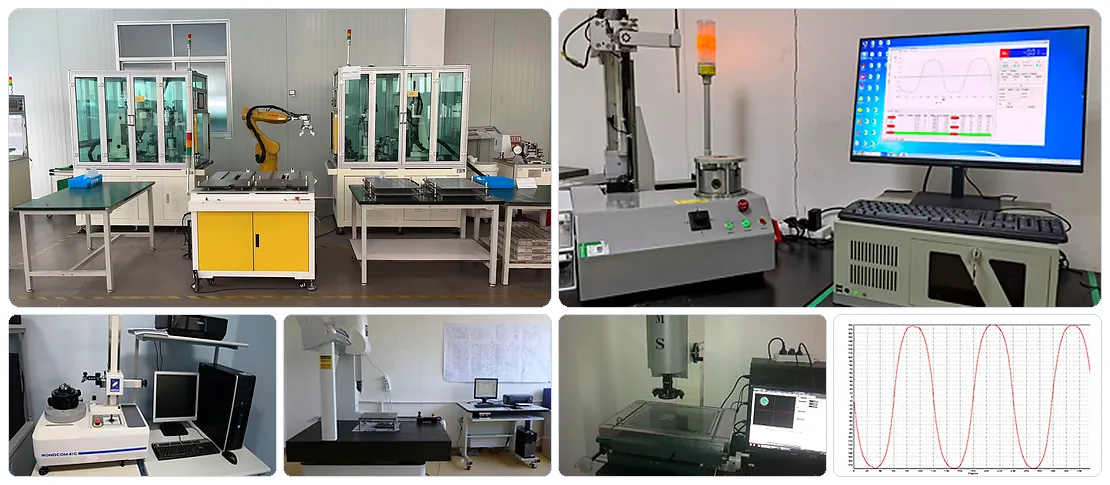
First-article inspection records OD, thickness, center bore or recess, flatness and axial or radial runout in mm against the released drawing. The measurement record identifies the datum, gauge or CMM setup and sample status.
Material reports record Br, Hcb, Hcj and (BH)max at 20°C. Finished discs are measured for surface field or flux at the stated fixture and air gap; TMR angle-sensor applications can use a 6–20 mT in-plane field target.
The approved drawing revision, compound batch, mold, magnetizing fixture and inspection result form the lot-release record. Projects that define signal output as critical can include 100% flux or field screening in the agreed inspection plan.
The first article links actual mm dimensions, magnetic results and the agreed test fixture to the released drawing revision.
Recurring lots follow the approved compound, tooling, magnetizing fixture and drawing-defined inspection characteristics.
GX supplies the approved bonded NdFeB disc and the drawing-defined magnetization, inspection and documentation scope.
Product and supply scope
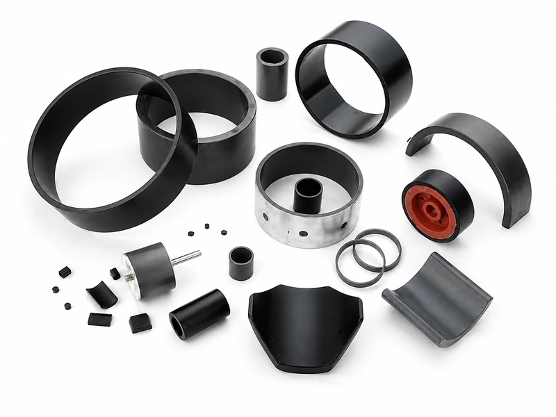
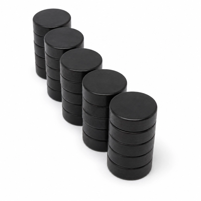
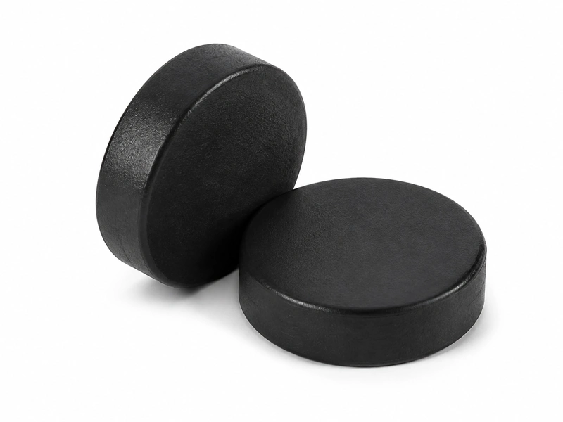
A bonded neodymium disc magnet is a flat circular magnetic component made from NdFeB magnetic powder and a polymer binder. GX reviews solid discs and drawing-defined center features by diameter, thickness, flatness, working face, magnetization direction and acceptance method.
Typical material screening for injection-molded bonded NdFeB uses Br 0.35–0.65 T, Hcj 600–1,200 kA/m and (BH)max 4–10 MGOe at 20°C. Finished-part output is released by the drawing-defined geometry, magnetization condition and measurement position.
Drawing variables
Disc quotation is reviewed around the features that affect molding, magnetization and inspection: diameter, thickness, flatness, center features, working face, magnetic direction and mating method.
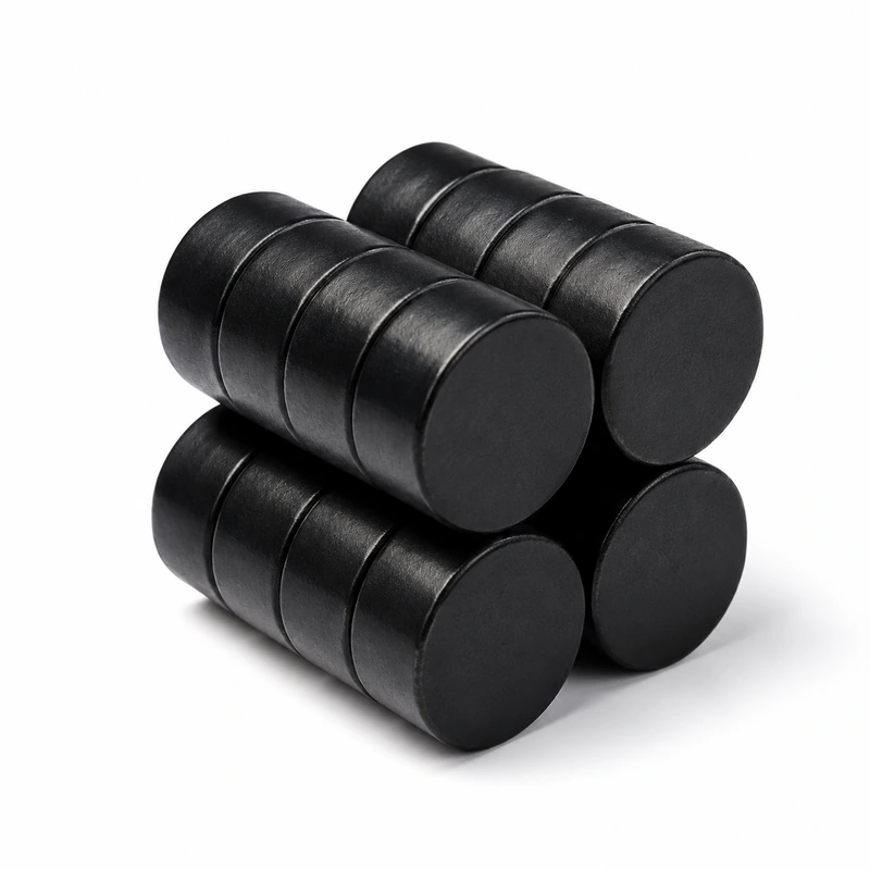
Technical parameters for quotation
Reference material ranges support early selection. Project values become supply commitments when the bonded NdFeB compound, disc geometry, magnetization, inspection method and release records are fixed in the drawing, quotation and acceptance plan.
| Parameter group | Project-specific review basis | Release basis |
|---|---|---|
| Material / Route | Bonded NdFeB compound, binder system, isotropic or anisotropic condition, injection or compression bonding route; Br, Hcj and (BH)max at 20°C when specified. | Approved material specification, released drawing and sample test record. |
| Geometry and Tolerances | Diameter, thickness, flatness, parallelism, edge condition, chamfer, center hole, recess and drawing datum used for inspection. | Released drawing, dimensional inspection method and first-article report. |
| Magnetic or Functional Requirement | Axial, diametric or drawing-defined magnetization; surface field, flux, pull force or functional response measured at the specified position. | Approved magnetic test method, fixture, air gap, temperature and acceptance limit. |
| Mechanical / Assembly Interface | Working face, bonding face, carrier pocket, locating feature, adhesive contact, retention surface and mating-part relationship. | Assembly interface drawing, fit requirement and retention or bonding validation when specified. |
| Operating Environment | Operating temperature range, humidity, corrosion medium, impact, vibration, adhesive exposure, nearby metal parts and opposing field. | Project specification, environmental test plan and pass criteria. |
| Inspection and Acceptance | Dimensional checks, appearance criteria, polarity check, magnetic output test, sampling quantity and inspection frequency. | Control plan, sample approval record and recurring lot-release record. |
| Supply Boundary | Bonded NdFeB disc magnet, agreed magnetization, inspection, packaging and documentation; additional assembly scope only when released. | Quotation, approved drawing and purchase specification. |
Project route
The project route connects the bonded NdFeB compound, disc geometry, forming route, datum scheme, magnetization direction and inspection method before the sample is released for customer approval.

Disc diameter, thickness, center features, working face, mating method and operating condition are reviewed from the drawing and RFQ input.
Bonded NdFeB compound, binder system, isotropic or anisotropic condition, and injection or compression bonding route are selected for the required geometry and magnetic target.
Parting line, shrinkage allowance, center feature, edge condition, inspection datum and measurement access are confirmed before tooling release.
The selected forming route defines molded features, edge finishing, center-hole or recess treatment, and any drawing-required secondary operation.
Axial, diametric or drawing-defined magnetization is checked together with polarity, surface field, flux or pull force at the agreed position and test condition.
Approved drawing revision, sample record, inspection method, acceptance limit and lot-release record are used to control repeat orders.
Verification
GX verifies disc dimensions, flatness, mating features, pole orientation and magnetic output against the released drawing and approved sample. Measurement conditions and acceptance limits are defined before recurring production so each batch is evaluated using the same criteria.
| Inspection item | Verification method | Why it matters to the buyer |
|---|---|---|
| Disc dimensions and flatness | Measure thickness, OD/ID, flatness, parallelism and datum features using the drawing-specified gauges or optical measurement method. | Maintains seating accuracy, assembly clearance and a consistent working air gap. |
| Mating interface | Verify position, concentricity, runout, press-fit retention or transmitted torque where required by the drawing. | Supports stable positioning and mechanical load transfer in the finished assembly. |
| Magnetic output | Measure flux, surface field, pole-to-pole output or functional waveform under the agreed fixture, air-gap and temperature conditions. | Confirms that production parts match the approved magnetic design and application response. |
| Polarity and pole pattern | Verify magnetization direction, pole count and pole sequence against the approved orientation drawing. | Prevents installation errors and incorrect sensor or motor commutation signals. |
| Appearance and edges | Inspect flash, chips, cracks, contamination and edge profile against the approved visual standard. | Reduces assembly interference and avoids appearance-related acceptance disputes. |
Application fit
Application fit is reviewed by disc geometry, working face, magnetization direction, operating condition and the way the magnet is retained in the customer assembly.

For position-sensing projects, define the disc diameter, thickness, working face, axial or diametric magnetization, target field position and sensor gap. Sample approval records dimensional results and magnetic response under the agreed test condition.

For compact actuators, the disc magnet is reviewed with the bonding face, carrier pocket or mechanical retention feature. Diameter, thickness, edge condition, pull force or flux target, temperature range and load direction are confirmed before sample release.

For instrument assemblies, flatness, edge condition, magnetic direction and corrosion exposure can affect fit and signal response. GX checks the disc against the drawing-defined dimensions, appearance criteria and magnetic acceptance method.

For carrier-mounted designs, the disc is evaluated together with the pocket, adhesive area, locating face or insert relationship. The released requirement defines disc geometry, working face, magnetization, retention method and inspection basis.
Quality-system support
GX Magnet applies its IATF 16949 quality system to drawing revision control, sample approval, inspection planning and lot-release records for bonded neodymium disc projects.
Disc diameter, thickness, center features, working face, magnetization direction and appearance criteria follow the approved drawing revision.
Sample records include dimensional results and agreed magnetic or functional checks before the part is released for recurring production.
Inspection scope, sampling quantity, gauge or fixture, measurement position and lot-release record are confirmed before recurring orders are released.
Project-specific certificates, inspection records and magnetic performance data can be provided during sample approval or project review according to the approved drawing and agreed acceptance criteria.
Buyer communication
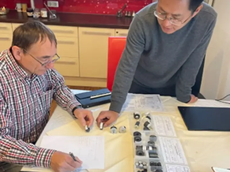
Use the buyer meeting to connect the drawing, mating component, working face and magnetic target before the RFQ is released. GX engineers can review disc diameter, thickness, center features, magnetization direction, operating condition and the inspection basis needed for sample approval.
Compare solid discs, center-featured discs, ring parts and molded magnetic components so the RFQ is directed to the correct product category and forming route.
Review diameter, thickness, flatness, datum scheme, mating face, adhesive area or carrier pocket together with the required axial or diametric magnetization.
Confirm the RFQ inputs for material selection, tooling review, sample quantity, inspection method, acceptance criteria and recurring lot-release-release records.
Engineering and sourcing FAQ
Answers to common engineering and sourcing questions about bonded neodymium disc magnet material selection, disc dimensions, magnetization direction, operating conditions, inspection methods and sample release.
The main differences are the material route, achievable geometry, magnetic output and assembly method. Compare them in the actual magnetic circuit and operating condition; the product name alone is not enough to select the part.
Start with NdFeB compound, binder and axial or diametric orientation. Then check the required magnetic output, geometry, temperature and commercial volume before fixing a grade in the drawing.
Control the dimensions that set fit, air gap or working position. For this product, review diameter, thickness, flatness, edge condition and magnetization direction; avoid applying a tight general tolerance to non-functional surfaces without a measurement reason.
Specify the magnetization axis or pole pattern, pole count where applicable, and the acceptance method. A field value must also state the measurement location, fixture or air gap so supplier and buyer evaluate the same condition.
Temperature capability depends on material grade, geometry, magnetizing state and the magnetic circuit. Provide temperature, corrosion medium, mechanical retention and magnetic circuit; GX can then review demagnetization risk and whether the proposed material route fits the duty.
Use an agreed method tied to the application: material-property testing, surface field at a defined position, flux, pull force, pole pattern or waveform. The released drawing and acceptance plan should state the instrument, fixture and limits.
Send the drawing or 3D model, material or magnetic target, diameter, thickness, flatness, edge condition and magnetization direction, temperature, corrosion medium, mechanical retention and magnetic circuit, expected quantity and acceptance method. State whether tooling, inserts, assembly or magnetization is included in the requested supply scope.
Agree the drawing revision, tooling state, critical dimensions and magnetic test method before sample release. Approval should identify the sample record and any deviations; recurring orders then follow the released specification, quotation and control plan.
Request for quotation
Include the application, 2D/3D drawing, magnetic target and test condition, operating environment, mating interfaces, sample quantity and annual demand.