

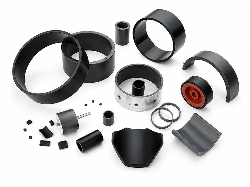
Thin-Wall and Mold-Filling Review
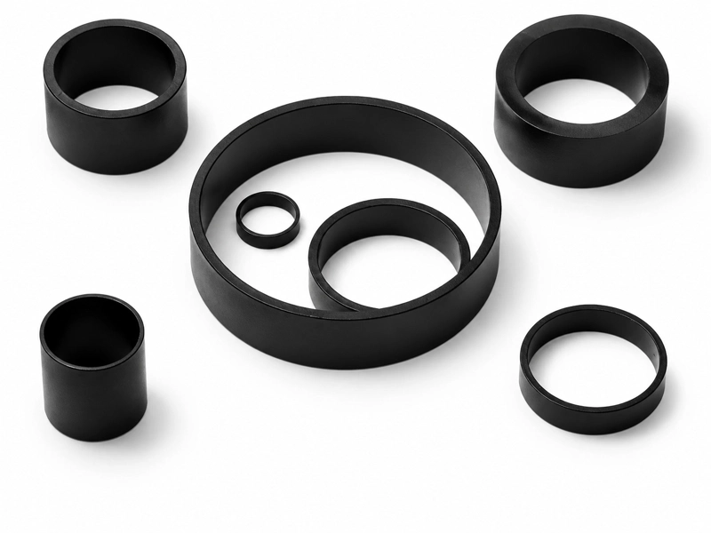
Wall sections down to approximately 0.3 mm can be evaluated as a project target. Feasibility depends on flow length, gate position, ribs, holes, powder loading, flash limits and dimensional-inspection access.
Injection Magnet · NdFeB Material
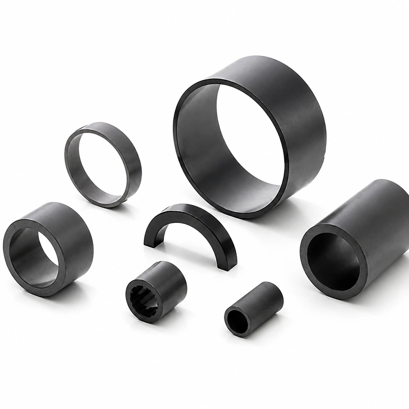
GX Magnet delivers drawing‑driven injection‑molded NdFeB components for compact motors, sensors and integrated magnet assemblies. We conduct full review of geometry, polymer binder selection, insert specifications, magnetization scheme and acceptance criteria prior to tooling release and sample validation.









Before quotation
A manufacturable quotation requires one revision-controlled package connecting molded geometry, compound, interfaces, operating conditions and acceptance. A product name or nominal size alone cannot define tooling feasibility or inspection requirements.
Why choose us for your project
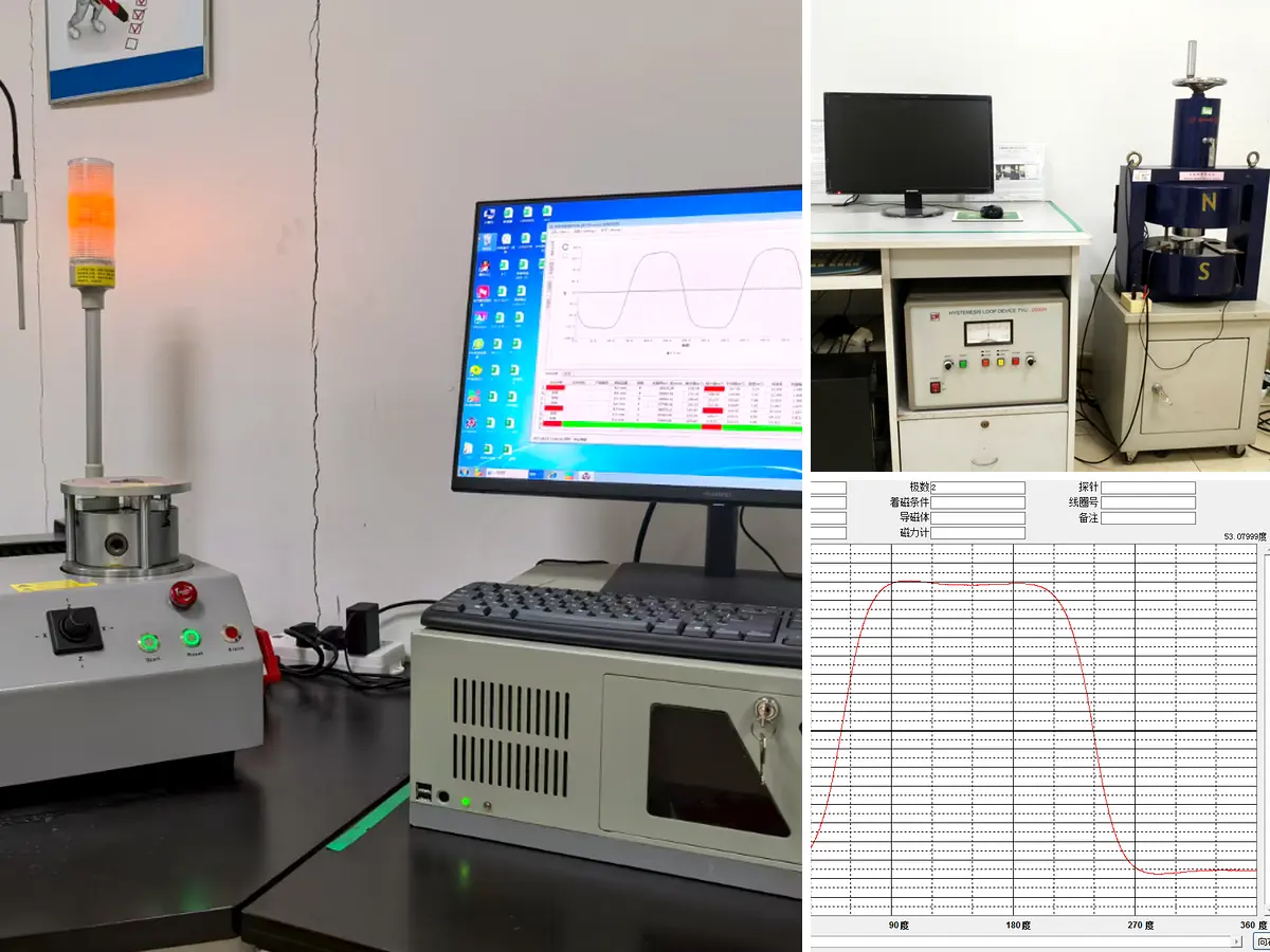
A common industry sourcing problem is that samples are approved against typical compound data, without minimum magnetic limits for recurring production. This can lead to lot-to-lot drift, irreversible flux loss at peak temperature, or moisture-related changes in dimensions and working air gap. GX addresses these risks by defining project-specific minimum limits and verifying finished-part magnetic output under specified measurement conditions.
Why choose us for your project
Injection‑molded NdFeB is chosen for geometries impossible with sintered magnets: ultra‑thin wall, insert over‑molding and high‑density multi‑pole patterns. Many vendors hit limits on minimum wall thickness, deliver uneven pole‑to‑pole flux, or reject insert‑molding requests. Mis‑comparison against sintered magnet performance often delays project definition.
Why choose us for your project
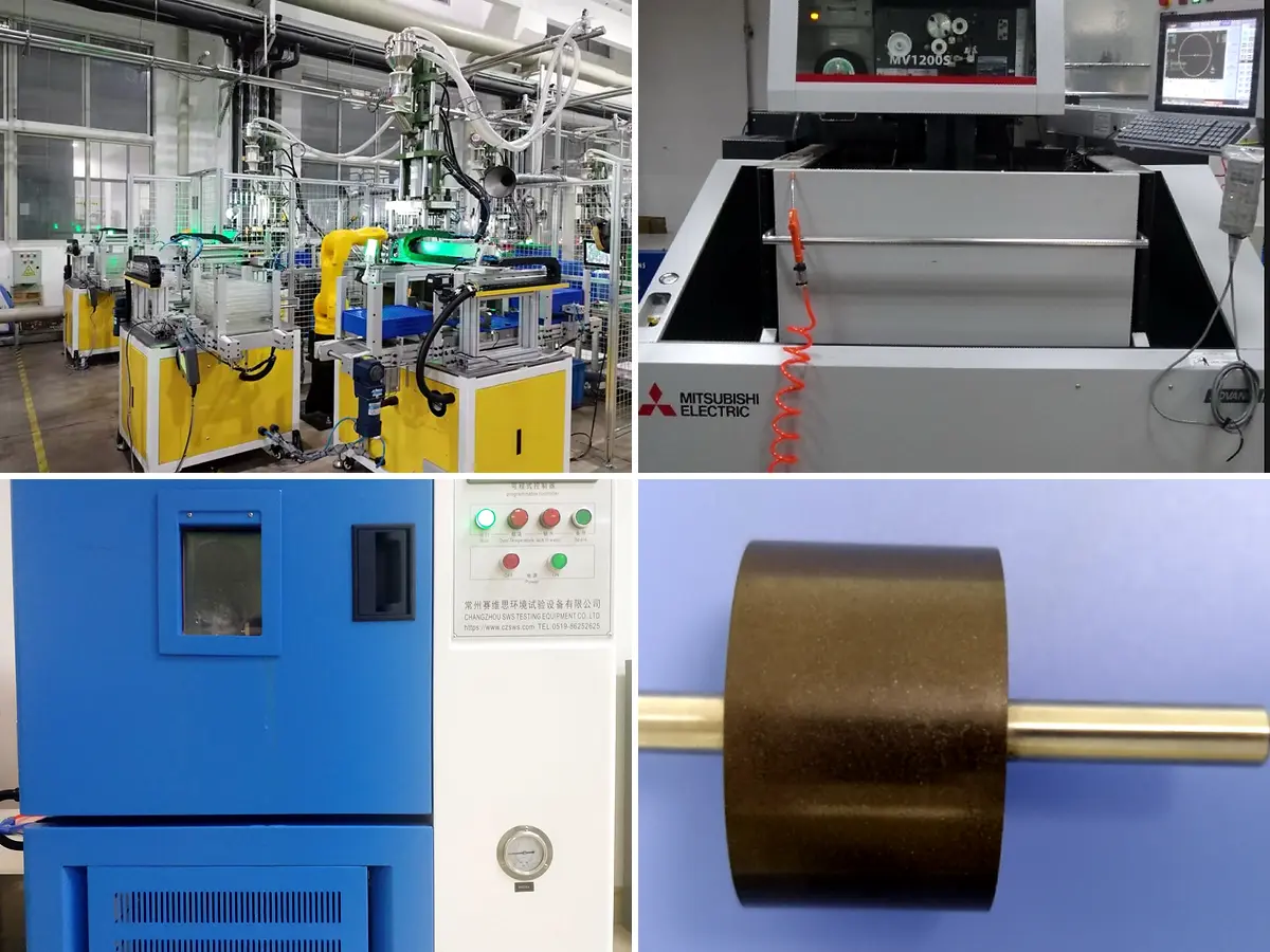
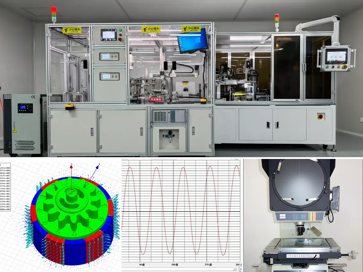
A conforming sample does not by itself prevent magnetic drift in recurring production.GX defines tool‑ownership & tool‑life terms at quotation. Every serial production lot delivers measured magnetic & dimensional inspection records based on guaranteed minimum specs. Archived FAI and SPC datasets support OEM and automotive‑grade project documentation requirements.
Product and supply scope
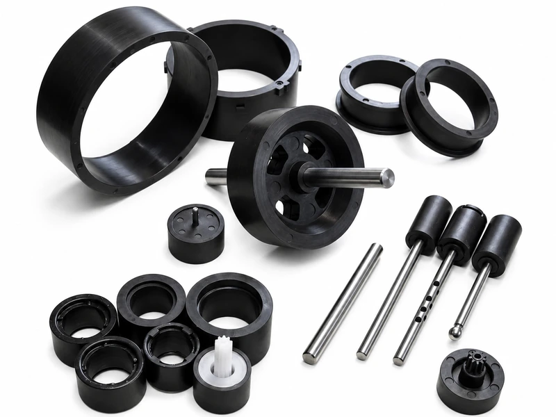
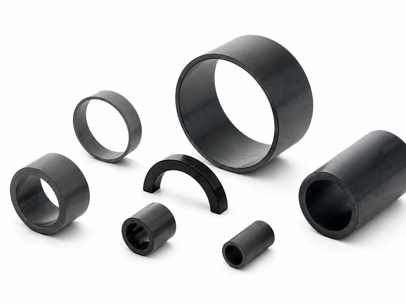
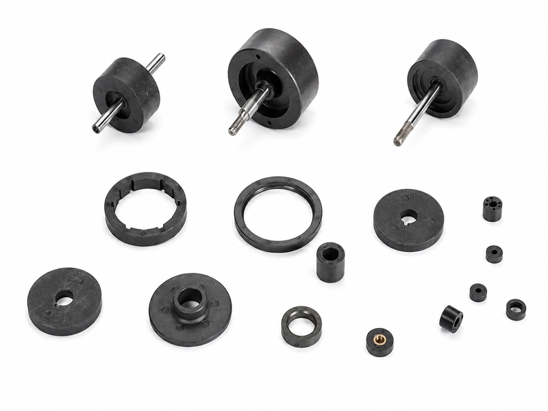
An injection‑molded NdFeB magnet blends neodymium‑iron‑boron magnetic powder with thermoplastic binder, then forms the compound within a mold. This process is specified for projects requiring repeatable net‑shape geometry, thin‑wall or integrated features, insert over‑molding, or custom magnetic layouts matched to final assembly requirements.
GX Magnet delivers custom injection‑molded NdFeB components per approved drawings and project specifications. Polymer matrix, magnetic grade, magnetization orientation, insert integration and final‑assembly‑related scope are all project‑specific and fully confirmed prior to quotation.
DRAWING AND TOOLING VARIABLES
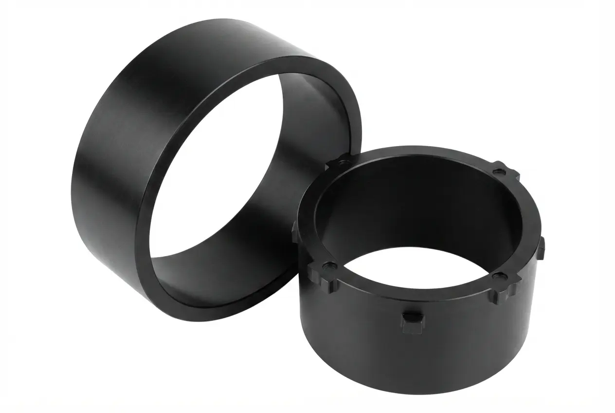
Injection-molded NdFeB combines magnetic material and mechanical interfaces in one molded component. Thin-wall feasibility, insert retention, magnetic-powder loading and pole-pattern acceptance must therefore be defined together before tooling and sample approval.

TECHNICAL PARAMETERS FOR QUOTATION
Use these reference ranges for initial engineering review. Final compound, dimensional, magnetic and inspection limits become supply commitments only when recorded in the released drawing, approved specification, quotation and acceptance plan.
| Parameter group | Project-Specific Engineering Review | Confirmation and Release Basis |
|---|---|---|
| Material / route | Injection-molded NdFeB with PA12, PA6/6 or PPS binder; approximately 65–90 wt% magnetic-powder loading and 3.4–5.5 g/cm³ density as reference ranges. Confirm compound grade and isotropic or anisotropic orientation. | Approved compound specification identifying binder, grade, orientation and required material-property limits. |
| Geometry and tolerances | Review the 2D/3D drawing for wall sections, ribs, holes, gates, flash limits, inserts, datums and mating dimensions. Wall sections down to approximately 0.3 mm may be evaluated subject to material flow, length and geometry. | Released drawing and FAI dimensional report. Thin-wall capability and tolerances are approved by part, not as universal limits. |
| Magnetic / Functional Output | Selection references: Br 0.35–0.65 T, Hcj 600–1,200 kA/m and (BH)max 4–10 MGOe. Review axial, radial or 2–64-pole magnetization and the required flux, surface field or waveform. | Approved minimum material limits plus finished-part magnetic limits, with measurement position, air gap, fixture, temperature and scan method defined. |
| Insert / Assembly Interface | Define shaft, hub or insert material, engagement length, molded position, runout, retention force and transmitted torque. | Approved assembly drawing, FAI results and pull-out, retention or torque test record when specified. |
| Operating environment | An approximate 100–150°C operating range may be considered by compound and binder grade. Confirm continuous and peak temperature, exposure time, moisture, chemicals, speed, load and external demagnetizing field. | Approved validation conditions with exposure duration, sample quantity and pass/fail criteria. |
| Inspection and acceptance | Define critical dimensions, insert position, appearance, polarity, pole pattern, flux or waveform checks, including gauge, fixture, sampling frequency and SPC requirements. | Control plan, sample or FAI report and lot-release inspection records. PPAP documentation is supplied when required by the customer program. |
| Supply boundary | Identify whether the quotation covers the molded magnet only or a drawing-defined insert-molded component, including tooling, magnetization, inspection, packaging and documentation. | The quotation and released drawing define the included scope. Shafts, hubs and downstream assembly are included only when explicitly stated. |
Project route
The project route aligns the compound, molded geometry, insert interface and magnetic acceptance criteria before the approved sample is transferred to recurring production.
Review the drawing revision, application, operating temperature, mating interface, pole pattern, annual demand and finished-part acceptance method.
Select the NdFeB powder grade, PA12 or PPS binder, powder loading, and isotropic or anisotropic orientation against magnetic, temperature, moisture and molding requirements.
Evaluate thin walls, ribs, gates, parting lines, shrinkage, datums, insert loading, mold release and measurement access before tooling approval.
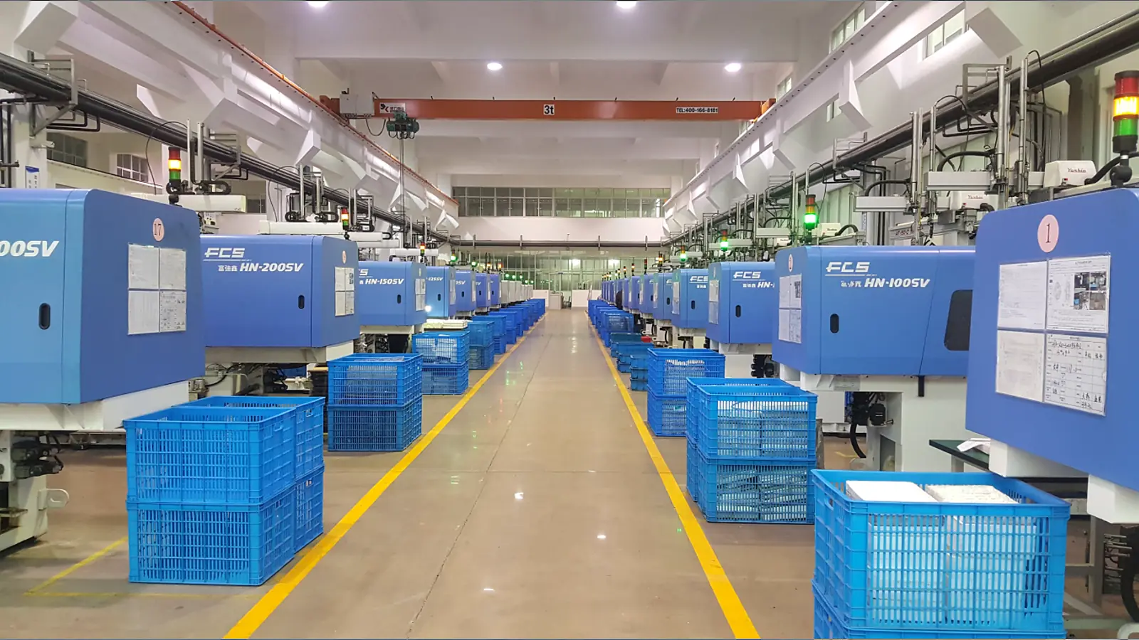
Produce tooling samples with the approved compound and inserts. Establish molding parameters, then inspect flash, critical dimensions, insert position and appearance.
Apply axial, radial or multipole magnetization as specified. Verify polarity, flux, surface field or waveform at the defined air gap, position and temperature, then complete FAI and sample approval.
Freeze the approved drawing, compound, molding and magnetizing parameters, inspection fixture and sampling frequency. Use control-plan, SPC and lot-release records; provide PPAP documentation when required by the customer program.
Verification
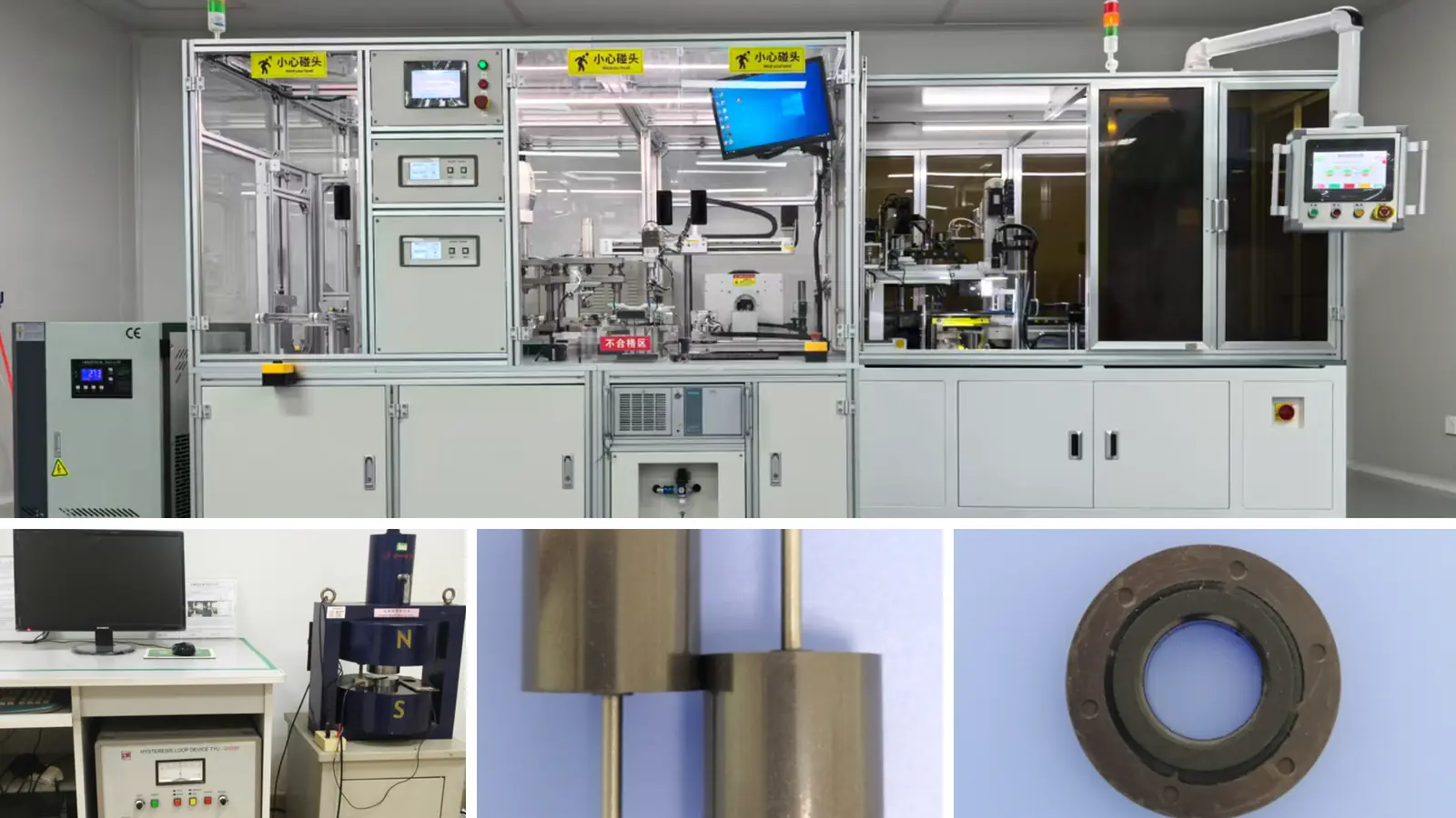
Critical dimensions, insert position, pole layout and finished-part magnetic response are verified against the same released drawing, approved sample and defined measurement conditions.
| Inspection item | Control approach | Why the buyer needs it |
|---|---|---|
| Molded Dimensions | OD, ID, wall thickness, datums, locating features and mating dimensions are checked using drawing-defined gauges or measurement methods. | Confirms assembly fit and the geometry that determines the working air gap. |
| Interface relationship | Insert position, runout, retention force or transmitted torque is checked when specified by the drawing. | Supports stable mechanical location and rotation in the mating assembly. |
| Polarity and Pole Layout | Magnetization direction, pole count, pole sequence and pole position are verified against the approved orientation drawing. | Reduces reverse installation, commutation and sensor-position errors. |
| Magnetic Output | Flux, surface field or multipole waveform is measured at the specified air gap, position, fixture and temperature. | Connects the finished component to its approved functional magnetic limits. |
| Molding Appearance | Flash, short shots, sink marks, surfaces and edges are evaluated against the approved sample or appearance standard. | Reduces assembly interference and subjective acceptance disputes. |
Application fit
Application suitability is determined by component geometry, magnetic pattern, operating conditions, assembly interface and required production repeatability.
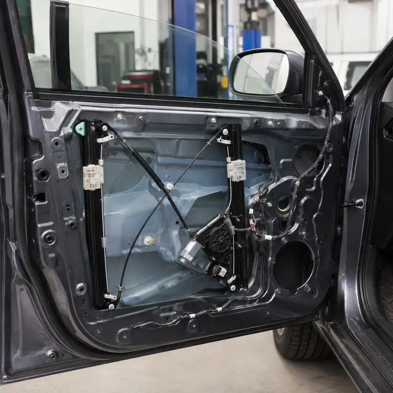
For compact motor rotors: specify thin‑wall geometry, locating interfaces, pole map, flux waveform, temperature, corrosion and rotational load. Tooling‑sample dimensions and magnetic performance are documented at sample approval.

For sensors & encoders: align magnet features with locating interfaces. Validate geometry, pole map, flux waveform, temperature, corrosion and rotational load. Sample performance and drawing revision are kept in release documents.
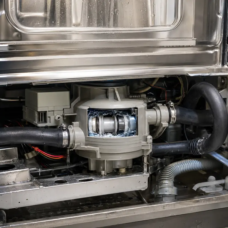
For pumps & small drives: thin‑wall features affect assembly fit and performance. Define locating interfaces, magnetic and environmental parameters. Approve tooling‑sample dimensions & magnetic output before mass production.

For integrated magnetic assemblies: define geometry, locating interfaces, magnetic profile and service conditions. Verify tooling‑sample dimensions and magnetic performance against released drawings.
Quality-system support
GX Magnet operates under the IATF 16949 quality system for drawing revision control, sample validation and project‑specific inspection planning.
Critical geometry, interfaces, pole layout and appearance criteria follow the approved drawing revision.
Prototype dimensions and agreed magnetic or functional checks are recorded before recurring production.
Inspection scope and sampling expectations are aligned before quotation and release.
Project‑specific certificates, inspection reports and magnetic‑performance data are available upon sample validation or project review, based on released drawings and agreed acceptance criteria.
Buyer communication
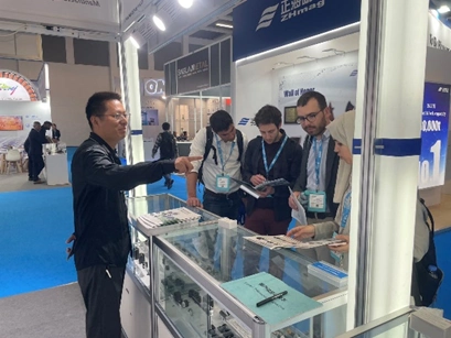
GX Magnet participates in global industrial exhibitions to demonstrate our magnetic materials, injection‑molded magnet components and motor‑component manufacturing capabilities for OEM engineers, product developers and sourcing stakeholders. You may bring project drawings, mating‑part data or magnetic‑performance requirements for on‑site consultation. Our technical team will assess material selection options, assembly‑interface risks and compile complete RFQ prerequisites to prepare for formal engineering review.
Compare part geometries, insert features and product configurations. We assess prototype feasibility and define baseline technical conditions prior to formal quotation initiation.
Review pole layout designs, mating interfaces, operating‑condition constraints and project‑specific validation requirements to align technical assumptions between both parties.
Align project milestones covering drawing review, golden‑sample approval, inspection‑report deliverables and structured ongoing technical communication throughout serial production.
GX Magnet
GX Magnet has manufactured ferrite materials since 1992. For injection-molded NdFeB projects, GX applies this magnetic-material and motor-component experience to compound selection, molded geometry, insert interfaces, magnetization and finished-part inspection.
NdFeB powder, PA12 or PPS binder, magnetic orientation, operating temperature and moisture exposure are reviewed before compound approval.
Thin walls, inserts, shrinkage, gates, datums and critical dimensions are evaluated before tooling release and sample molding.
Polarity, flux or multipole waveform, FAI results and the control plan connect the approved sample to recurring production.
Engineering and sourcing FAQ
Find practical answers on manufacturing-route selection, NdFeB compound and binder choice, molded geometry, insert integration, multipole magnetization, operating conditions, inspection, tooling and recurring production.
The main differences are the material route, achievable geometry, magnetic output and assembly method. Compare them in the actual magnetic circuit and operating condition; the product name alone is not enough to select the part.
Start with NdFeB compound, polymer binder and orientation method. Then check the required magnetic output, geometry, temperature and commercial volume before fixing a grade in the drawing.
Control the dimensions that set fit, air gap or working position. For this product, review thin-wall geometry, inserts, critical dimensions, pole pattern and air gap; avoid applying a tight general tolerance to non-functional surfaces without a measurement reason.
Specify the magnetization axis or pole pattern, pole count where applicable, and the acceptance method. A field value must also state the measurement location, fixture or air gap so supplier and buyer evaluate the same condition.
Temperature capability depends on material grade, geometry, magnetizing state and the magnetic circuit. Provide temperature, corrosion medium, rotational load and opposing field; GX can then review demagnetization risk and whether the proposed material route fits the duty.
Use an agreed method tied to the application: material-property testing, surface field at a defined position, flux, pull force, pole pattern or waveform. The released drawing and acceptance plan should state the instrument, fixture and limits.
Send the drawing or 3D model, material or magnetic target, thin-wall geometry, inserts, critical dimensions, pole pattern and air gap, temperature, corrosion medium, rotational load and opposing field, expected quantity and acceptance method. State whether tooling, inserts, assembly or magnetization is included in the requested supply scope.
Agree the drawing revision, tooling state, critical dimensions and magnetic test method before sample release. Approval should identify the sample record and any deviations; recurring orders then follow the released specification, quotation and control plan.
Request for quotation
Include the application, 2D/3D drawing, magnetic target and test condition, operating environment, mating interfaces, sample quantity and annual demand.