GX MAGNET Logo

Injection Magnet · Ferrite Material

Injection Molded Ferrite Magnets Manufacturer

GX Magnet manufactures injection-molded ferrite components to customer drawings for OEM motors, sensors and magnetic assemblies, including complex molded geometries and parts with integrated inserts. Geometry, polymer requirements, mating interfaces and magnetization are reviewed before tooling; critical molded dimensions and finished-part magnetic response are verified during sample approval.

  • Ferrite magnetic powder combined with a polymer binder
  • Custom geometry, inserts and pole patterns reviewed by drawing
  • Prototype-to-volume control under an IATF 16949 quality system
Supply statement: project-specific molded ferrite components
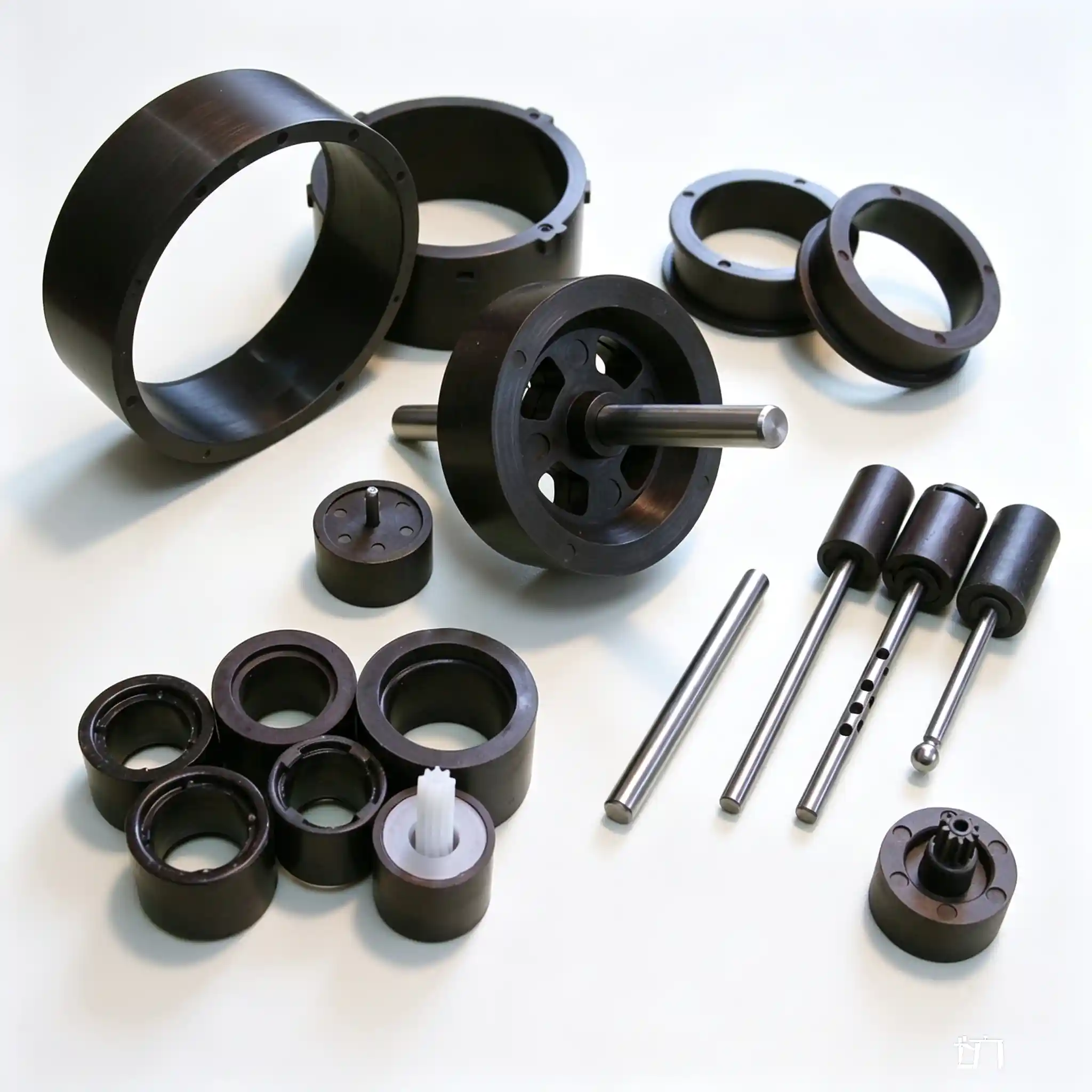
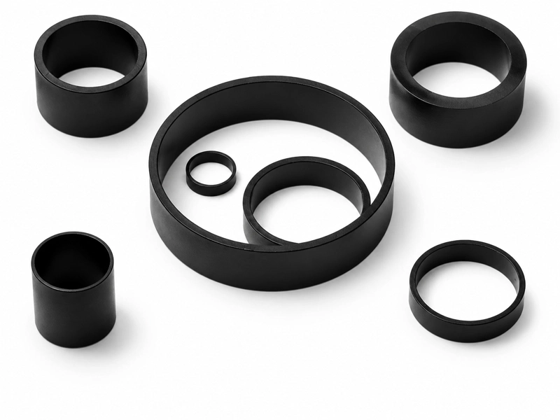
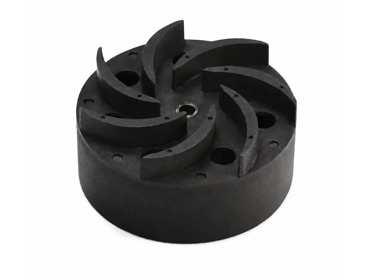
Injection molded ferrite magnet component produced to a customer drawing

30+ Years Supporting Injection-Molded Ferrite Programs

Bosch logo
Midea logo
Siemens logo
WEG logo
Gree logo
Shimge logo
Copreci logo
Buhler logo
Samsung logo
Nidec logo

FOR A FASTER QUOTATION

Inputs for a Faster Injection-Molded Ferrite Quote

These inputs help GX evaluate molding feasibility, tooling, compound and magnetization requirements, and the inspection scope needed to prepare the quotation and sample plan.

Drawing, Molded Geometry and InterfacesSend the 2D/3D drawing and revision, including wall thicknesses, ribs, holes, inserts, datums, critical tolerances, flash limits and mating dimensions.
Material and Magnetic FunctionState any polymer-system or compound constraints, magnetic orientation, magnetization direction and pole pattern. Define the required field, flux, waveform or sensor response together with the measurement position and air gap.
Application and Operating ConditionsDescribe the application, mating components, working air gap, temperature, media exposure, mechanical load, vibration and external demagnetizing field.
Volume and Acceptance RequirementsProvide the sample quantity, expected annual demand and drawing revision, together with dimensional, appearance and magnetic acceptance criteria and any required inspection records.

ASSEMBLY-DRIVEN MOLDING

Precision Compensation For Complex Geometry & Insert Over‑Molding

Most magnet manufacturers only handle simple ring shapes. We solve molding risks at the design phase: mold shrinkage simulation, insert position calibration and thin‑wall feasibility review before tooling starts.

  • Mold Shrinkage Pre‑compensation: Simulate ferrite‑polymer shrinkage, pre‑correct cavity dimension to avoid assembly mismatch after molding.
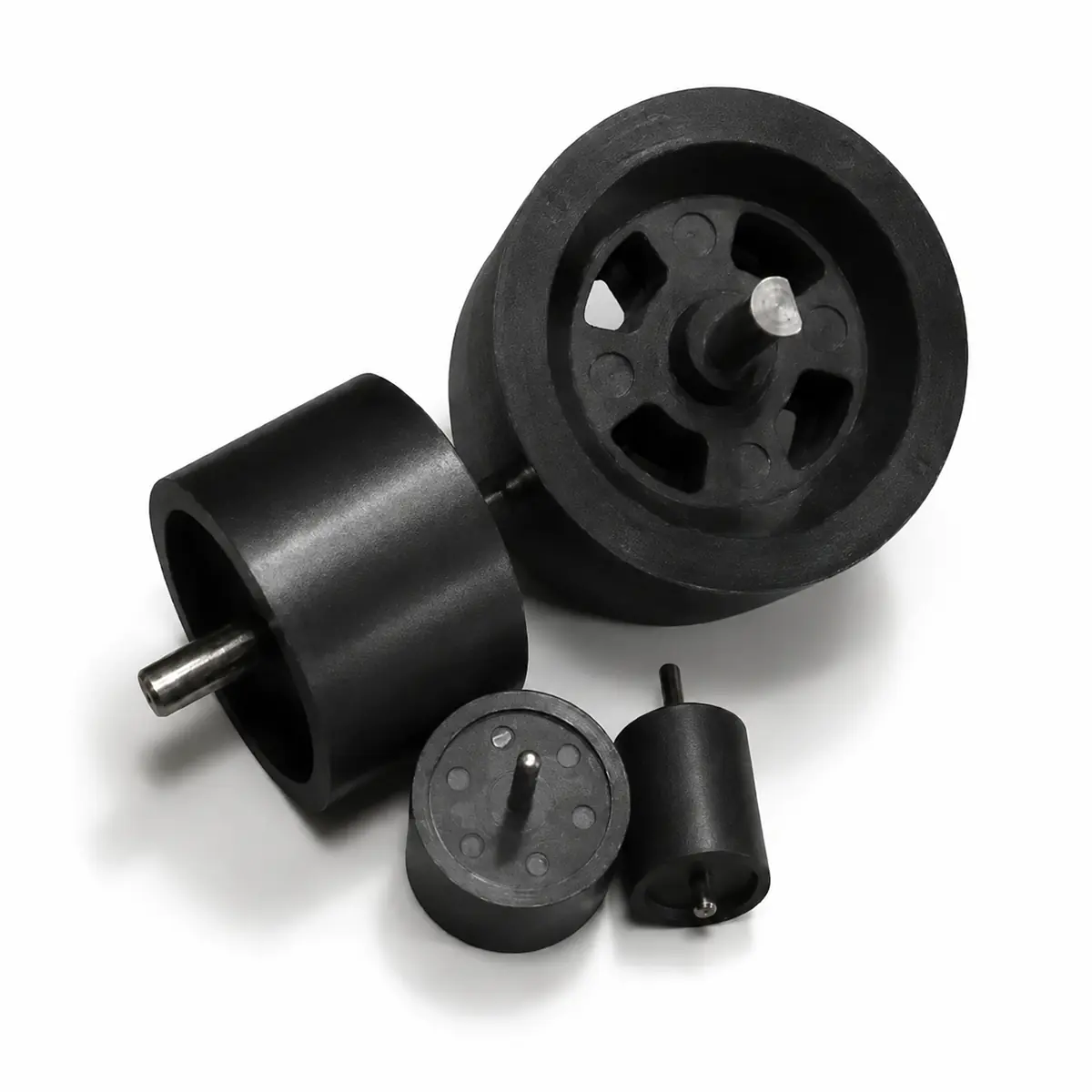
  • Insert Over‑molding Capability: Integrate metal shaft / metal sleeve in one injection shot, eliminate secondary assembly tolerance stack‑up.
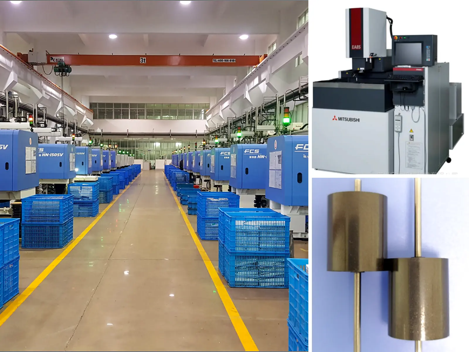
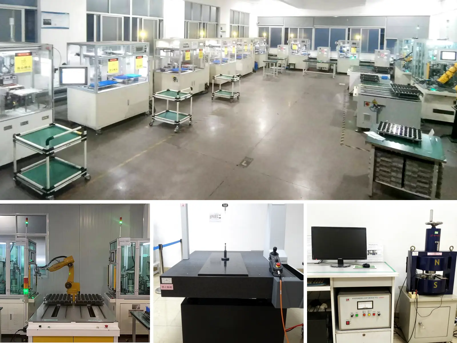
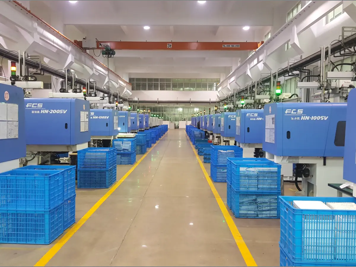
Injection Molded Ferrite Magnet manufacturing route and process control

FINISHED-PART MAGNETIC FUNCTION

Controllable Multi‑pole Magnetization & Uniform Flux Output

Poor pole‑position accuracy & uneven flux are common pain‑points for injection ferrite. Our in‑house magnetization tooling and magnetic simulation guarantee stable magnetic response for sensor and BLDC motor applications.

  • 2‑64 Poles In‑mold Magnetization: Complete multi‑pole magnetization during injection cycle, reduce post‑magnetization position deviation.
  • Uniform Inter‑pole Flux Consistency: Strict flux variation control across poles, avoid signal jump for rotary position sensors.

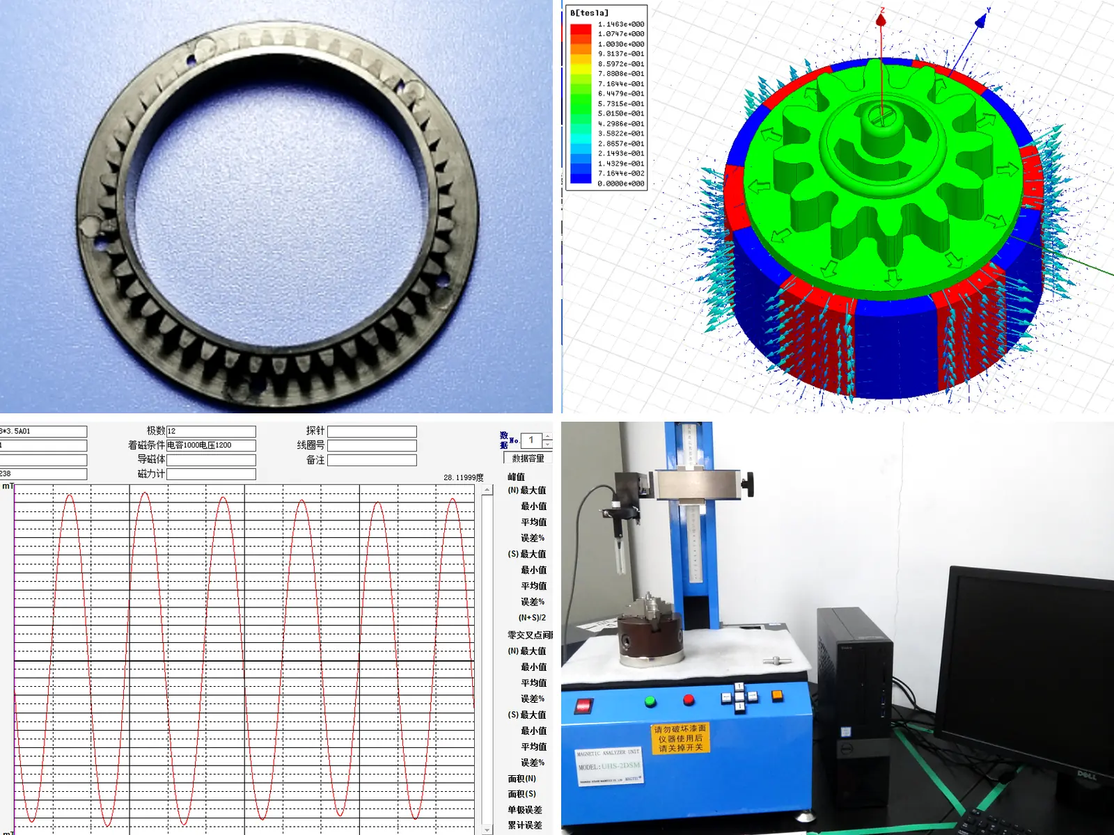
Every new project validates magnetic curve on pre‑production samples before mass release.

Injection Molded Ferrite Magnet inspection and project validation

SAMPLE-TO-PRODUCTION CONTROL

Carry Approved Geometry and Magnetic Limits into Production

Injection-molded magnets can vary through compound condition, molding parameters, insert position and magnetizing settings. GX uses the released drawing, approved sample and control plan to connect molded dimensions, insert location and magnetic acceptance with recurring production. Automated loading, positioning, overmolding, magnetization and inspection are applied on suitable programs to reduce manual handling and support lot-to-lot consistency

  • Up to 500,000 Pieces per Day: Recorded automated magnetizing capacity reaches up to 500,000 pieces per day on applicable injection-magnet lines.
  • Proven High-Volume Program: One recorded gimbal and security-camera ring program, OD 10.2 × L16.7 mm, reached 200,000 pieces per shift and 12 million pieces per month.
Injection Molded Ferrite Magnet manufacturing route and process control

Product and supply scope

What Is an Injection Molded Ferrite Magnet?

An injection-molded ferrite magnet is a permanent magnet produced by molding a ferrite-filled polymer compound. This process is selected when a component requires complex molded geometry, locating features, integrated inserts or a defined multipole pattern that would be difficult to achieve with a conventional sintered ferrite part.

GX manufactures drawing-based injection-molded ferrite components for motors, pumps, sensors and actuators. Polymer-system requirements, molded shrinkage, critical datums, insert position, magnetization and finished-part acceptance are reviewed before tooling and sample approval. The quotation defines whether GX supplies the molded magnet only or an approved insert-molded component; shafts, hubs, carriers, electronics and final assemblies are identified separately when included.

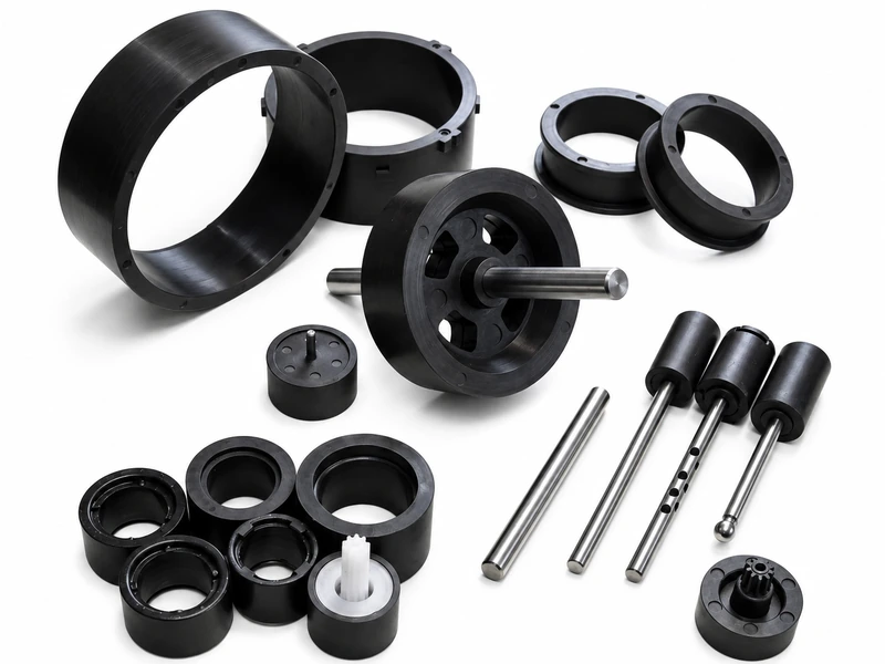
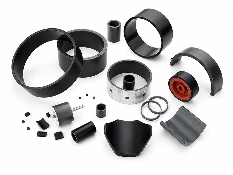
Custom injection molded ferrite component with integrated geometry
Molded Around the InterfaceThe drawing defines wall thicknesses, locating features, inserts, critical datums, shrinkage acceptance and mating dimensions before tooling.
Magnetic Function DefinedMagnetic orientation, magnetization direction, pole pattern and field, flux or waveform targets are matched to the installed position and working air gap.
Application Conditions ReviewedThe polymer system and molded design are reviewed against temperature, moisture, contact media, speed and mechanical load.
Consistency from Sample to ProductionApproved samples and measurable criteria control critical dimensions, insert position, appearance, polarity and magnetic response in recurring production.

DESIGN INPUTS BEFORE TOOLING

Define the Compound, Inserts and Pole Pattern Before Tooling

GX supplies injection-molded ferrite components using PPS, PA66 or PA12 polymer systems with approximately 65–90 wt% magnetic-powder loading. The final compound, molded geometry, insert interface and pole pattern are selected according to the required magnetic output, mechanical conditions and molding process.

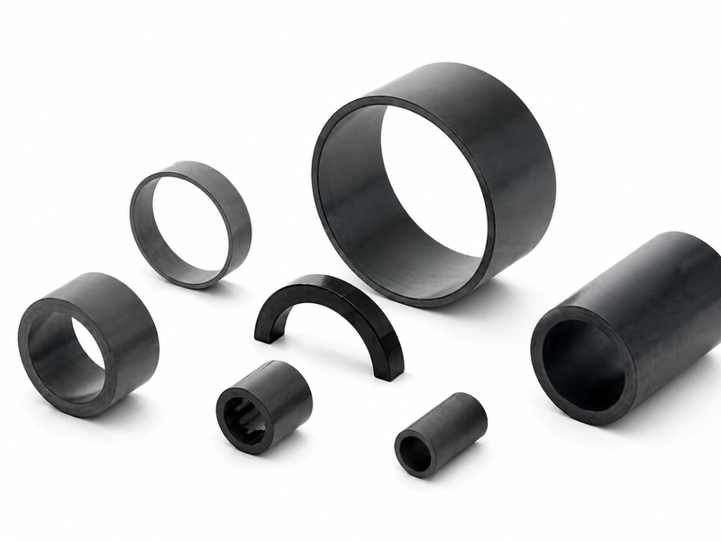
Drawing-defined injection molded ferrite magnet geometry

Polymer System and Powder Loading

Select PPS, PA66 or PA12 according to the operating temperature, moisture, chemical exposure and mechanical requirements. Magnetic-powder loading is reviewed within an approximate 65–90 wt% range and released with the project-specific formulation.

Critical Molded Dimensions

Specify wall thicknesses, ribs, holes, flash limits, insert position, shrinkage-sensitive dimensions and inspection datums. Measurement access and the required gauge, fixture or CMM method are reviewed before tooling.

Shaft, Hub or Sleeve Integration

Define the insert material, diameter, embedded length, axial position, runout and retention method. Pull-out force or transmitted-torque limits are included when required by the assembly drawing.

2–64-Pole Magnetization and Acceptance

Define pole count, pole pitch, pole position and magnetization direction within the applicable 2–64-pole range. Finished parts can be inspected for polarity, surface field, flux or waveform at the specified air gap, fixture, position and temperature.

Technical parameters for quotation

Define Injection-Molded Ferrite Requirements for Quotation and Sampling

GX reviews the ferrite-polymer compound, molded geometry, insert interface and finished-part magnetic output as one specification. GX supply supports PPS, PA66 (PA6/6) and PA12 systems, approximately 65–90 wt% magnetic-powder loading and 2–64-pole magnetization for applicable projects. Final values are confirmed through the released drawing, approved samples and agreed inspection plan.

Parameter groupProject-specific review basisConfirmation and Release Basis
Material / Molding RouteSelect PPS, PA66 or PA12 and approximately 65–90 wt% magnetic-powder loading according to magnetic output, molded strength and operating conditions. Confirm isotropic or anisotropic compound and the required orientation route.Approved compound specification records the polymer system, powder loading and orientation condition; material-property data is provided at the agreed test temperature when specified.
Geometry and tolerancesDefine wall sections, ribs, holes, molded datums, insert position, flash limits, shrinkage-sensitive dimensions and mating tolerances.Released drawing establishes dimensions, datums and tolerances; first-article inspection verifies the critical molded features and assembly fit.
Magnetic / Functional RequirementSpecify magnetization direction, polarity and a 2–64-pole pattern where applicable. Define field, flux, pole position or waveform at the stated air gap and measurement position.Approved sample report records the pole count, measurement air gap, position, fixture, temperature and finished-part magnetic limits.
Shaft / Insert InterfaceDefine shaft, hub or sleeve material, mating dimensions, embedded length, runout, retention method and any pull-out-force or transmitted-torque requirement.Assembly drawing confirms the insert interface; dimensional, pull-out, retention or torque testing is completed when specified.
Operating EnvironmentState operating temperature, moisture, chemical exposure, mechanical load, speed and magnetic-circuit conditions.Validation plan defines the applicable exposure conditions, test duration and pass criteria for the selected compound and component.
Inspection and acceptanceConfirm dimensional and visual limits together with polarity, field, flux or waveform inspection and the required sampling frequency.Control plan identifies the gauge or fixture, measurement method, sample size, inspection frequency and lot-release records.
Supply ScopeSupply may cover a molded ferrite magnet or a drawing-defined insert-molded component with an integrated shaft, hub or sleeve.Quotation and released drawing identify all supplied components and the included molding, magnetization, inspection, packaging and documentation.

Project route

From Drawing DFM‑Review To Consistent Serial Production

Every project passes material compound selection, mold feasibility assessment, magnetic simulation, magnetization planning and formal inspection validation before volume release.

01

Requirement & DFM Review

Drawing, operating environment, pole‑magnetization pattern, mating interfaces, mechanical constraints and volume demands are jointly validated in early‑stage DFM review.

02

Magnetic Compound Evaluation

Ferrite‑polymer thermoplastic compound is selected and evaluated, matched against target magnetic performance, temperature resistance and mechanical operating limits.

03

Tooling & Mold Feasibility Review

Evaluate parting line, gate position, mold shrinkage compensation, datum definition, insert over‑molding layout and metrology access for inspection.

04

Injection Molding & Secondary Finishing

Injection molding executed under locked process parameters; qualified secondary finishing operations are performed where drawing specifications require.

05

Magnetization & First‑Article Validation

Pole pattern, dimensional tolerance, visual quality and mating‑interface performance are fully verified; FAI report issued prior to sample approval.

06

Serial Production & Batch Control

Mass production strictly follows approved drawing revision, sample standard and inspection criteria to guarantee lot‑to‑lot repeatability.

VERIFICATION AND LOT RELEASE

From Approved Drawing to Controlled Lot Release

GX converts the released drawing and approved sample into a project-specific control plan. Molded dimensions, insert position, mechanical retention, pole pattern, magnetic output and appearance are checked using defined gauges, fixtures and test conditions. Recurring lots are released only after the specified inspection results meet the approved acceptance limits.

PROJECT-DEFINED INSPECTION CHECKPOINTS
Inspection itemControl and Verification MethodControlled Risk
Molded Dimensions and DatumsCritical dimensions, wall sections, holes, datums, flash limits and insert positions are checked by CMM, gauges or project-specific fixtures.Controls assembly fit, working air gap and component location.
Insert Interface and RetentionShaft, hub or sleeve position, runout and mating dimensions are measured; pull-out force, retention force or transmitted torque is tested when specified.Reduces insert displacement, unstable rotation and mechanical-interface failure.
Pole Pattern and Magnetic OutputFor applicable 2–64-pole parts, GX verifies polarity, pole count, pole position, surface field, flux or waveform at the defined air gap and measurement position.Prevents reversed polarity, incorrect pole sequence and inconsistent motor or sensor response.
Appearance and Molding ConditionFlash, short shots, exposed inserts, cracks, surface condition and edge defects are evaluated against the approved visual standard.Reduces assembly interference and disputes caused by molding defects.
Application-Specific ValidationTemperature exposure, humidity, thermal cycling, retention or functional testing is completed when included in the approved validation plan.Confirms that the released material and component remain suitable under the specified operating conditions.

Application fit

Where Injection-Molded Ferrite Components Fit

Match the molded geometry, insert interface, pole pattern and operating conditions to the application.

Injection molded ferrite component reviewed for automotive auxiliary motors

Automotive Auxiliary Motors

Insert-molded ferrite rotors for pumps, fans and actuators. Define shaft or hub fit, pole count, magnetic output, temperature and vibration before sample approval.

Injection molded ferrite component reviewed for appliance and pump drives

Pumps and Appliance Drives

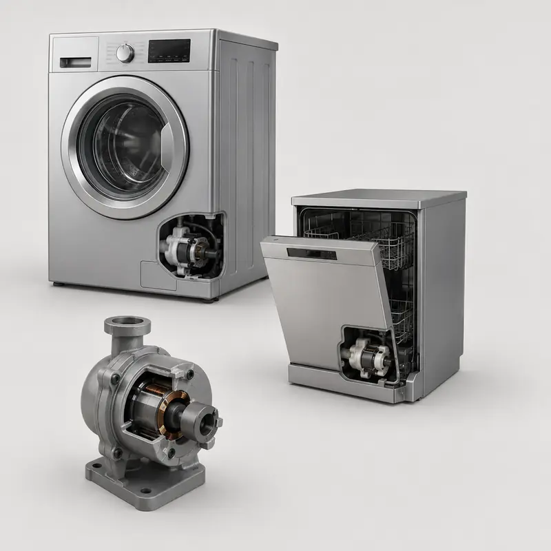
For circulation, drainage and appliance drives, review the rotor interface, working medium, temperature and pole pattern. Verify fit and magnetic output against the approved sample.

Injection molded ferrite sensor component

Sensors and Encoders

Molded magnetic targets with integrated hubs or shafts for position and speed sensing. Define pole position, air gap, field or waveform, and required sensor response.

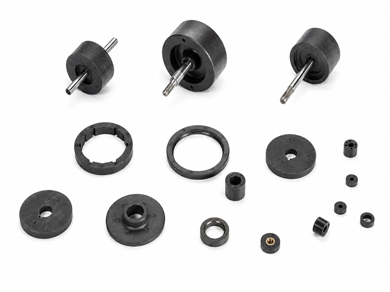
Custom molded ferrite magnetic assembly component

Compact Magnetic Assemblies

Thin-wall or insert-molded ferrite parts for compact motors, drones and electromechanical assemblies. Review molded features, insert retention, pole pattern and mechanical load.

Quality evidence

Inspection Records & Traceability for Injection Molded Ferrite Parts

GX Magnet runs full operations under IATF 16949 quality‑management system. All product releases are strictly bound to controlled drawing revisions, approved samples and predefined inspection specifications.

Revision Control

Critical dimensions, mating interfaces, multi‑pole layout and visual requirements are strictly governed by locked drawing revisions to avoid version deviation.

Sample Approval

Full first‑article‑inspection (FAI) records covering dimensional measurements, magnetic‑performance data and functional‑test results are archived prior to serial‑production approval.

Production Batch Traceability

Fixed inspection scope & sampling plans are aligned at quotation phase. Every production batch carries traceable records for full‑life‑cycle quality lookup.

Project‑specific conformance documents, batch inspection records and magnetic performance test data can be provided during sample approval or project review, based on the approved drawing and agreed acceptance criteria.

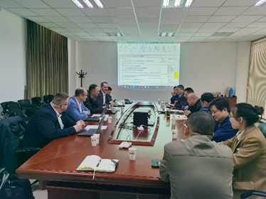
GX Magnet industrial exhibition discussion and ferrite samples

Exhibition presence

Review Ferrite Molding Projects With GX Engineers

GX Magnet uses industrial exhibitions to present ferrite materials, molded magnetic components and motor-part capabilities to OEM buyers, engineers and sourcing teams.

Sample Review

Compare molded geometries, inserts and ferrite product forms before choosing the quotation route.

Engineering Discussion

Review pole patterns, mating interfaces, environment and validation expectations with the project context.

Supplier Evaluation

Use the meeting to plan drawing review, sample approval, inspection evidence and recurring-production communication.

Manufacturing background

Ferrite Manufacturing and Motor-Component Support Since 1992

Founded in 1992, GX combines ferrite-material experience with injection molding, 2–64-pole magnetization and finished-part magnetic inspection. GX supply supports PPS, PA66 and PA12 compounds with approximately 65–90 wt% magnetic-powder loading, selected according to project requirements.

GX Magnet injection molded ferrite component for OEM supplier review

Engineering and sourcing FAQ

Common Questions About 
Injection-Molded Ferrite Magnets

Eight practical answers covering ferrite-polymer compound selection, molded geometry, insert integration, multipole magnetization, operating conditions, sample approval and inspection requirements for recurring production.

How do Injection molded ferrite magnets differ from molded ferrite and sintered ferrite parts?

The main differences are the material route, achievable geometry, magnetic output and assembly method. Compare them in the actual magnetic circuit and operating condition; the product name alone is not enough to select the part.

How should engineers select the material for Injection molded ferrite magnets?

Start with ferrite loading, polymer binder and orientation method. Then check the required magnetic output, geometry, temperature and commercial volume before fixing a grade in the drawing.

Which dimensions should be toleranced on Injection molded ferrite magnets?

Control the dimensions that set fit, air gap or working position. For this product, review tooling geometry, inserts, tolerances, pole pattern and mating interface; avoid applying a tight general tolerance to non-functional surfaces without a measurement reason.

What magnetization information is needed for Injection molded ferrite magnets?

Specify the magnetization axis or pole pattern, pole count where applicable, and the acceptance method. A field value must also state the measurement location, fixture or air gap so supplier and buyer evaluate the same condition.

How does temperature affect Injection molded ferrite magnets?

Temperature capability depends on material grade, geometry, magnetizing state and the magnetic circuit. Provide temperature, media exposure, mechanical stress and magnetic circuit; GX can then review demagnetization risk and whether the proposed material route fits the duty.

How should magnetic performance be verified for Injection molded ferrite magnets?

Use an agreed method tied to the application: material-property testing, surface field at a defined position, flux, pull force, pole pattern or waveform. The released drawing and acceptance plan should state the instrument, fixture and limits.

What information should an RFQ for Injection molded ferrite magnets include?

Send the drawing or 3D model, material or magnetic target, tooling geometry, inserts, tolerances, pole pattern and mating interface, temperature, media exposure, mechanical stress and magnetic circuit, expected quantity and acceptance method. State whether tooling, inserts, assembly or magnetization is included in the requested supply scope.

How are samples approved before recurring Injection molded ferrite magnets orders?

Agree the drawing revision, tooling state, critical dimensions and magnetic test method before sample release. Approval should identify the sample record and any deviations; recurring orders then follow the released specification, quotation and control plan.

Project inquiry

Request a Quote for Custom Injection Molded Ferrite Magnets

Attach the part and mating-assembly drawings. GX reviews geometry, material-system requirements, magnetization, interfaces, operating conditions and inspection methods before defining the sample route.

  • 2D / 3D drawing
  • Critical dimensions and datums
  • Pole pattern and magnetic target
  • Application, environment and annual demand

No file selected

By submitting this form, you agree to provide accurate project information for evaluation. Information is kept confidential.