

Powder preparation
Ball Milling
Mills prepare ferrite powder for forming. Particle-size distribution and slurry condition are important inputs to the pressing process.
GX Magnet · Production & Inspection
Our equipment supports sintered ferrite magnets, sintered NdFeB magnets, injection-molded magnets and magnetic assemblies. Explore the production lines, machining equipment and test instruments behind these products.

01 Sintered hard ferrite
Our ferrite production route starts with in-house powder preparation and continues through pressing, sintering and grinding. Equipment is selected for rings, arc segments, blocks and other ceramic magnet geometries.

Powder production
Our rotary kiln calcines the raw-material mixture used to make hard ferrite powder. Preparing powder in-house lets the material team work directly with the pressing and sintering operations.
Mills prepare ferrite powder for forming. Particle-size distribution and slurry condition are important inputs to the pressing process.

For anisotropic ferrite parts, wet presses compact slurry in an aligning magnetic field. Dewatering and tool geometry are controlled during forming.

Dry presses compact prepared powder into the required shape. The selected route depends on the geometry and magnetic requirements.

Furnace processing develops the ceramic structure of the pressed part. Shrinkage must be allowed for in the tooling and finishing plan.

Grinding brings sintered parts to their finished dimensions and prepares the surfaces needed for mating or assembly.
02 Sintered NdFeB
Our NdFeB equipment includes electric pressing, automated transfer into the sintering stage and three surface-application routes for grain boundary diffusion. These operations serve different purposes and are chosen around the magnet specification.
Production line
The line combines forming equipment with handling and furnace loading systems. Controlled transfer reduces repeated manual handling between pressing and sintering.

Electric control of forming and demolding loads supports repeatable handling of pressed NdFeB parts before sintering.

Screen printing applies diffusion-source material to selected magnet surfaces before the grain boundary diffusion heat-treatment stage.

PVD provides a vacuum-based route for depositing diffusion-source material. Deposition is a preparation step, not the diffusion heat treatment itself.

Spraying offers another route for applying diffusion-source material. Coverage and the process route are selected for the magnet geometry.
Grain boundary diffusion results depend on the base grade, magnet thickness, diffusion source and heat-treatment conditions. Equipment capability alone does not establish a finished magnet’s temperature rating.
03 Injection-molded magnets
Our horizontal, vertical and rotary-table injection molding arrangements support ferrite- and NdFeB-based compounds. Mold geometry, insert position and the magnetization plan are considered together for magnetic rings, rotors and shaped components.
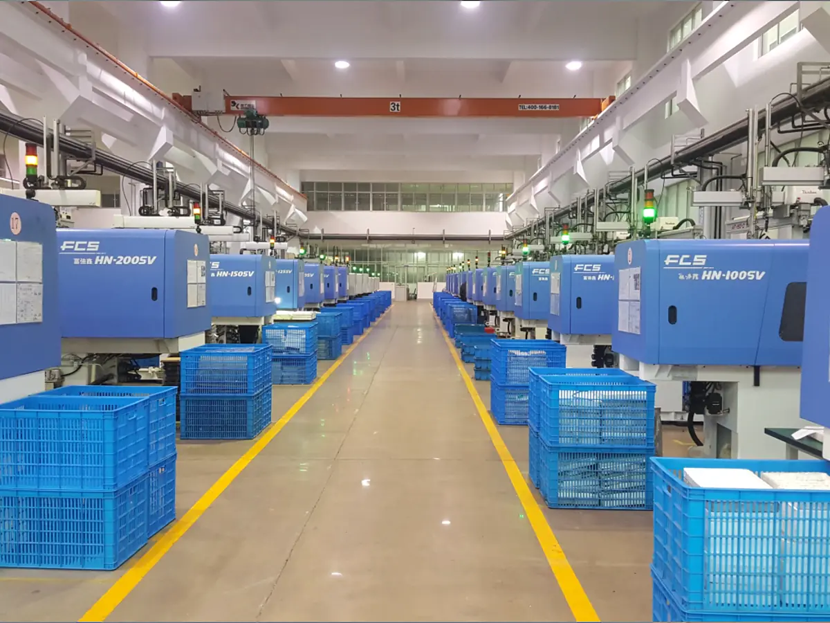
Horizontal presses support repeat production of molded magnet geometries using magnetic-powder and polymer compounds.

Vertical machines provide access for loading shafts, bushings and other inserts when the part calls for insert molding.

Molding cells combine the press with part-handling equipment to reduce manual transfer between cycles.

Dedicated handling arrangements are matched to the molded part and its next operation, rather than used as a single setup for every product.
04 Finishing · Tooling · Assembly
Magnet production does not end at the pressed or molded shape. Ferrite grinding, metal-component machining, toolmaking and assembly equipment establish the finished dimensions and interfaces. Magnetizing equipment supplies the field needed to magnetize the selected material and pole pattern.

Turning equipment machines cylindrical parts, fitting diameters and interfaces for housings and motor components.

Progressive-die presses manufacture stamped parts for motor cores and housings. Die condition and geometry are central to dimensional control.

Assembly equipment brings prepared components together in the sequence required by the stator design.

Forms steel motor housings using dedicated stamping dies. Housing geometry, mounting features and dimensional consistency are controlled to meet drawing requirements.

Wire electrical discharge machining produces detailed profiles in electrically conductive die and mold components.

Sinker EDM machines cavities and features in conductive tooling materials that are difficult to produce by conventional cutting alone.
05 Magnetic · Dimensional · Environmental
We use different instruments for material properties, finished-part magnetic output, physical geometry and application-related evaluation. The approved inspection plan identifies the characteristic, fixture, conditions and acceptance criteria.

Measures hysteresis behavior and derived parameters, including Br, Hcb, Hcj and (BH)max, using the configured sample holder and test method.

A fluxmeter and calibrated coil measure magnetic output. A Helmholtz-coil setup determines magnetic moment; the reported quantity depends on the coil, calibration and measurement procedure.

Checks the field waveform around multipole parts to evaluate pole count, position and consistency using the defined measurement setup.

Checks elemental composition to support material analysis. Composition results are separate from a finished magnet’s flux or waveform.

Examines prepared material sections to support investigation of microstructure and process-related features.

Checks three-dimensional geometry, positions and datum-related features on suitable parts.

Supports dimensional inspection of visible part features with the installed optical measurement setup. The measurement method is selected for the feature being checked.

Evaluates circular form on applicable rings, shafts and cylindrical components.

Checks specified gear geometry on relevant motor or transmission components.

Screens the visible characteristics configured for the part. AOI is not a substitute for magnetic-property testing or internal-defect evaluation.

Supports agreed thermal exposure or cycling tests. Magnetic changes are measured before and after the specified test where required.

Evaluates corrosion behavior against a defined exposure method, duration and acceptance criterion.

Checks hardness on suitable metal components as required by the component specification.

Supports evaluation of packaging and components under the selected transport simulation conditions.

Measures motor-system output on the configured test setup. Torque and speed describe the tested motor system, rather than the magnet material on its own.
The measurement method matters. A material-grade result, magnetic flux reading, field waveform and motor test do not measure the same characteristic. Reports should identify the sample, method and test conditions so results can be compared meaningfully.
Discuss the production route
Share the material, drawing, magnetic requirements and inspection criteria. We can discuss which equipment and process route fit the part, and what needs to be confirmed before sampling.