
NdFeB Arc MagnetManufacturer
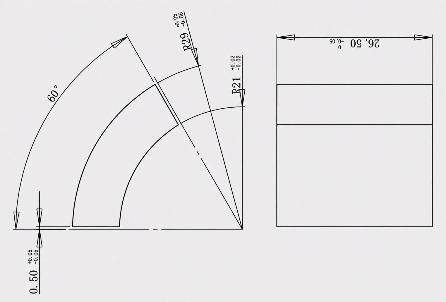
GX Magnet supplies custom sintered NdFeB arc magnets for permanent-magnet motors and other curved magnetic-circuit assemblies. Each segment is specified by its inner and outer radii, arc angle, radial thickness, axial length, magnetization configuration and installation conditions.
- Arc angle, inner radius, outer radius and axial length reviewed to the motor or assembly drawing
- NdFeB material requirement and magnetization direction considered with the required curved magnetic circuit
- Segment fit, surface requirement and sample scope established before recurring supply planning






Arc angle, inner and outer radii, and radial thickness
Segment position, air gap and assembly reference
Defined according to the curved magnetic circuit
Drawing, sample scope and supply requirements
NdFeB Arc Magnet Solutionsby Project Stage
Projects may begin with a released motor drawing, an existing sample or only a magnetic-circuit target. GX organizes the technical review around the available inputs and the requirements of the final assembly.
Build-to-Print Arc Segments
For buyers with an established motor or rotor drawing.
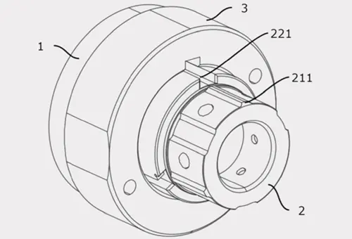
Rotor-Fit Review
For projects where arc magnets must locate accurately within a rotor or curved carrier.
Curved Magnetic-Circuit Requirements
For projects with a defined magnetic target but an incomplete magnet specification.
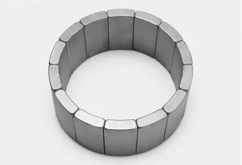
Sample-to-Repeat Supply Planning
For OEM programs moving from qualification samples to subsequent supply.
NdFeB Arc Magnet Product Options
GX delivers full-spectrum drawing-defined NdFeB arc segments — from standard geometries to skewed, matched-set and custom-profile configurations. All solutions are optimized for your exact geometry, magnetization target, material grade and assembly interface.
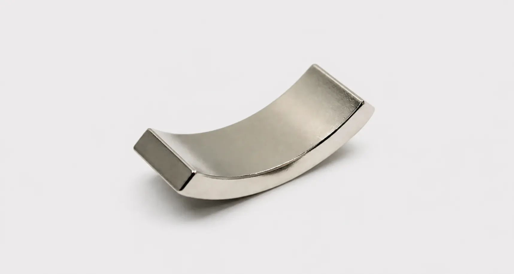
Standard NdFeB Arc Segments
- • Curved segments with defined inner and outer radii and arc angle
- • Commonly specified for permanent-magnet motor rotors and stators
- • GX verifies all critical dimensions & fit tolerance for direct rotor/stator assembly
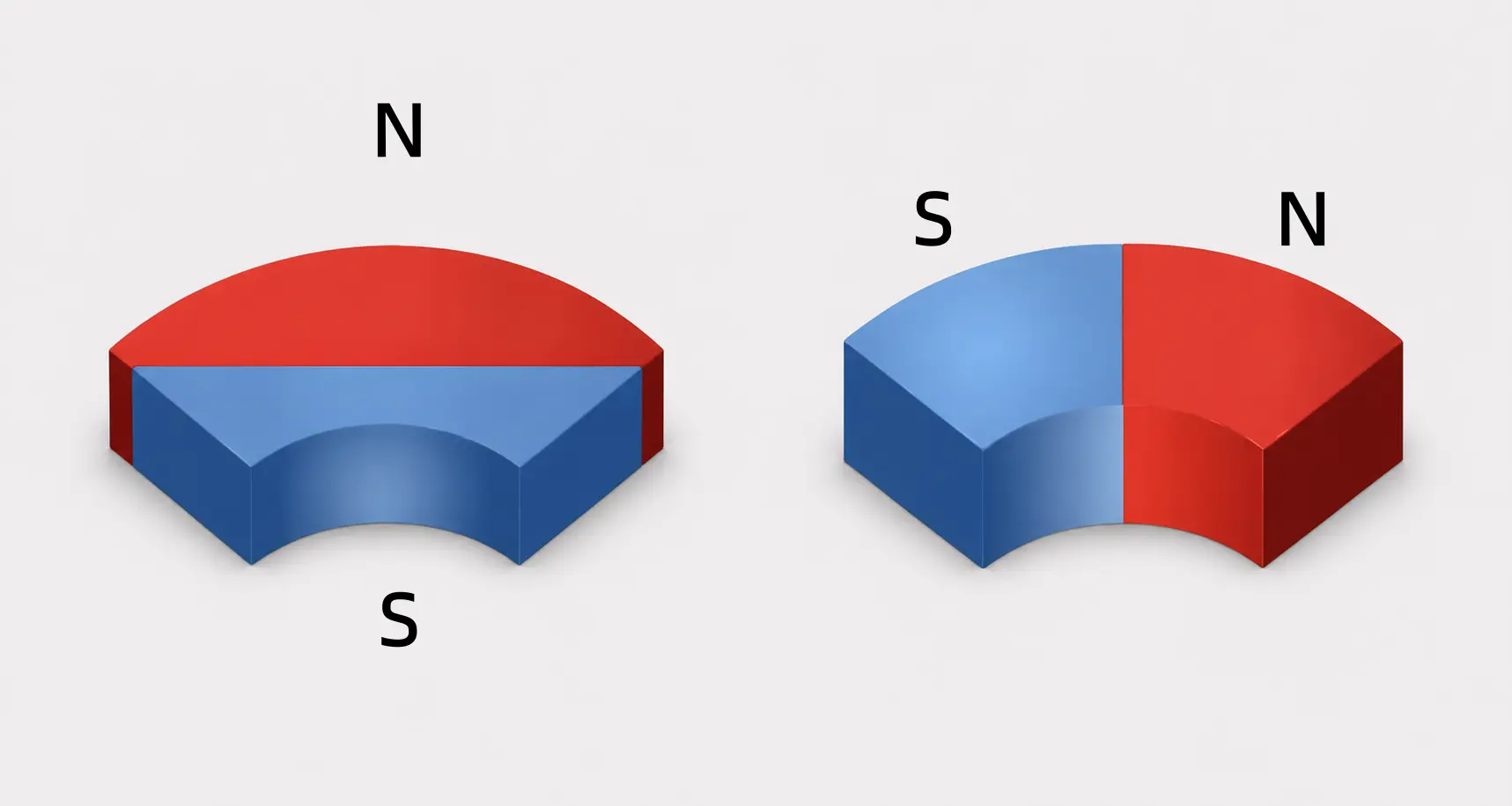
Radially Magnetized Arc Magnets
- • Arc magnets with magnetization defined for a radial motor magnetic circuit
- • Used where the pole direction must follow the rotor or stator structure
- • Precision pole alignment & magnetic consistency optimized for motor efficiency
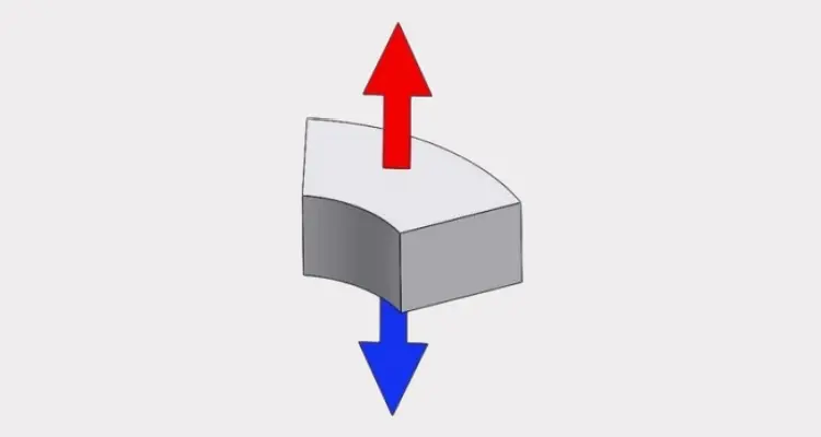
Axially Magnetized Arc Magnets
- • Curved NdFeB segments with an axial magnetization requirement
- • Used where the specified flux direction is parallel to the magnet axis
- • Path-matched axial magnetization tailored to your curved magnetic circuit design
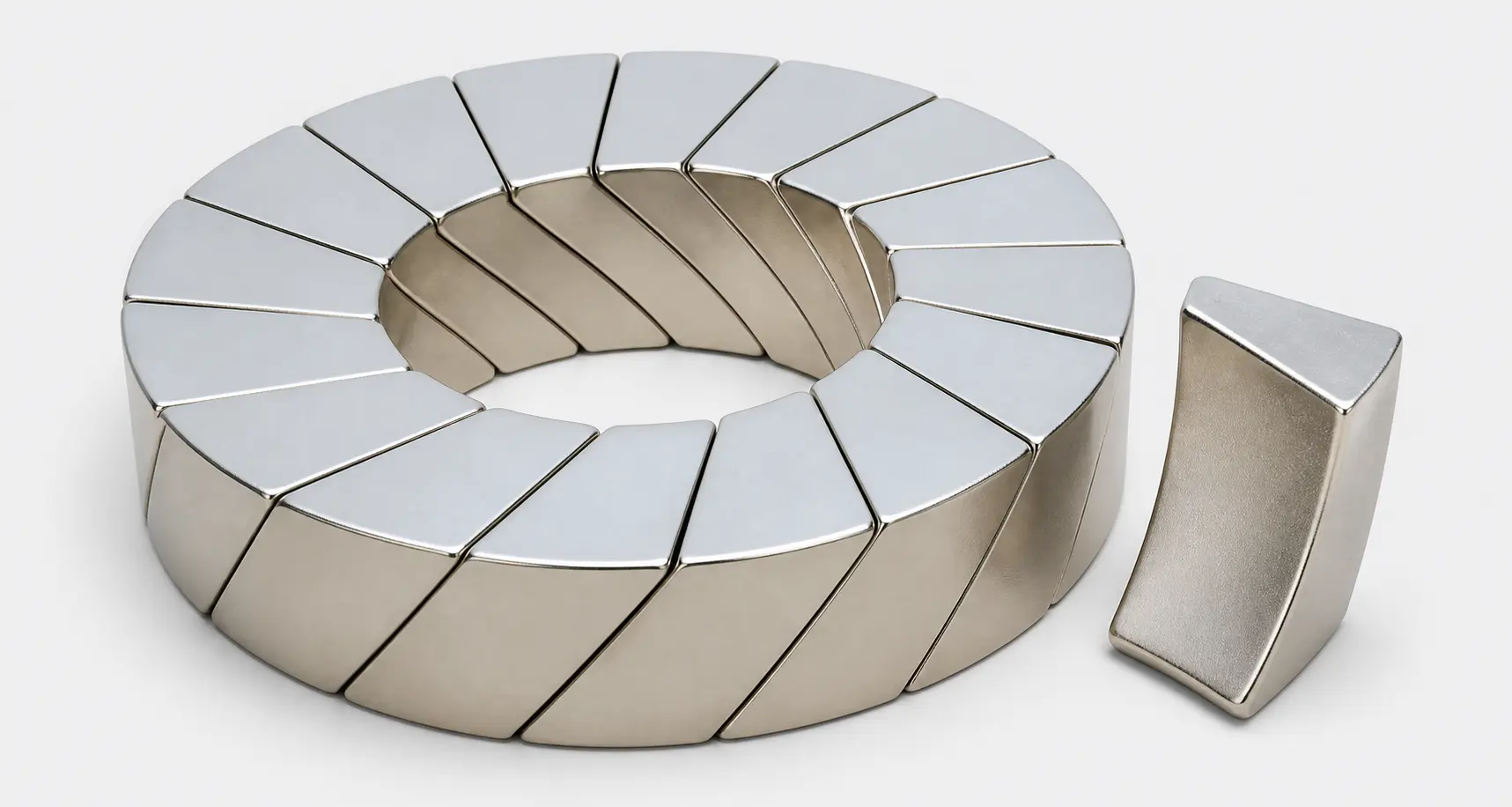
Skewed NdFeB Arc Segments
- • Arc segments incorporating a drawing-defined skew profile
- • Considered for motor designs with specified rotor or stator alignment requirements
- • Precision skew profile controlled to suppress cogging torque and reduce noise
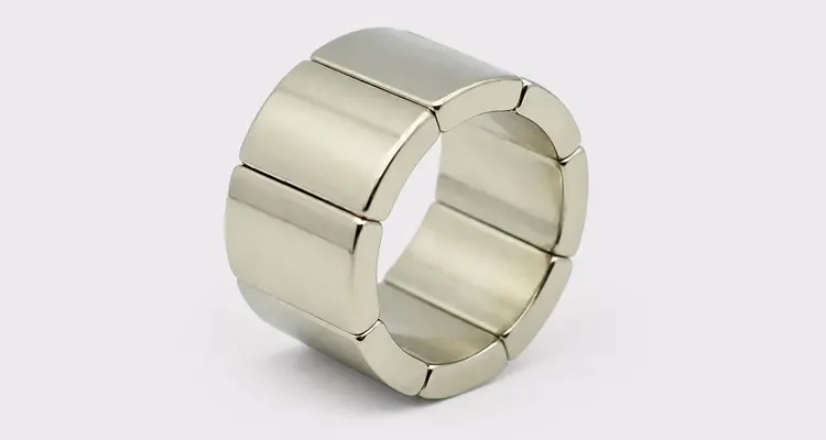
Multi-Segment Arc Magnet Sets
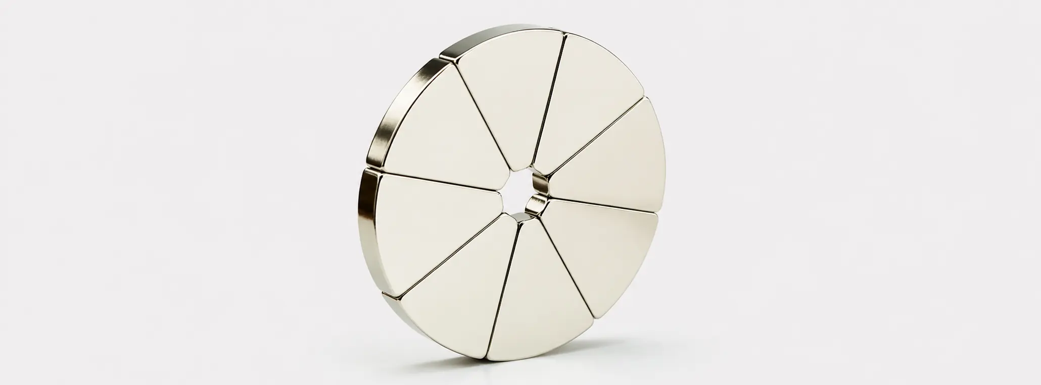
- • Matched arc segments specified as part of one circular magnetic assembly
- • Used where segment count, spacing and pole sequence must work together
- • Matched sets with consistent gap & polarity for seamless circular magnetic assembly
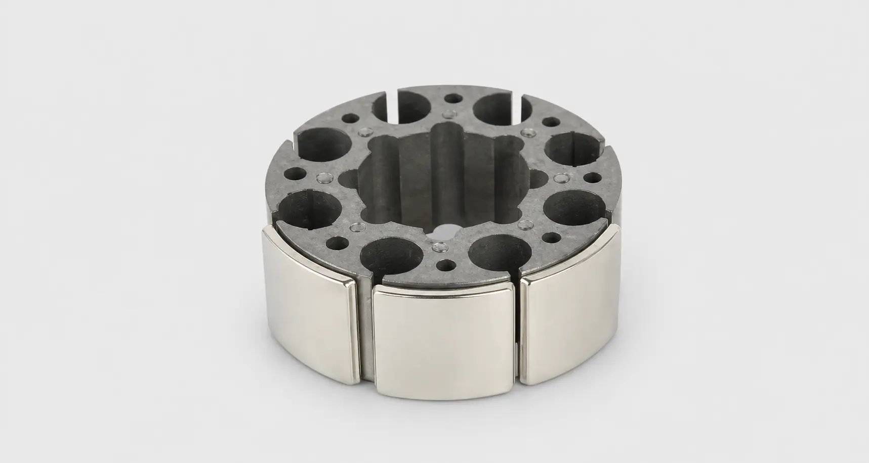
Custom-Profile NdFeB Arc Magnets
- • Drawing-defined arc magnets with non-standard edges, steps, slots or mounting features
- • Suitable for curved magnetic circuits with specialized assembly interfaces
- • Full custom geometries with mounting features, validated via rapid prototyping
Why Choose GX for NdFeB Arc Magnets?
Focused on the engineering and supply of sintered NdFeB arc magnets, GX supports global motor programs through application engineering, consistent quality and flexible delivery.
Engineering-Led Customization for Motor-Specific Requirements
GX connects the motor drawing, magnetic circuit and operating conditions to a practical arc-magnet specification for quotation, sampling and production review.
From Motor Requirements to Manufacturable Specifications
GX works directly from motor and assembly drawings to translate system requirements into manufacturable NdFeB arc magnet specifications. The review covers mounting interfaces, air-gap conditions, magnet position and operating requirements. Available configurations include radial or axial magnetization, skewed segment layouts and drawing-defined mounting features, helping reduce repeated drawing revisions before sampling.
Broad Grade and Geometry Coverage
Material options include standard N grades and elevated-coercivity M, H, SH, UH and EH families, including commonly specified grades such as N35, N40 and 35M. Grade selection is evaluated against the operating temperature, magnetic circuit, load line and required resistance to irreversible demagnetization. GX also supports blocks, discs, arc segments and drawing-defined special geometries.
Surface Protection for Different Environments
Surface protection options include zinc plating, Ni-Cu-Ni plating and epoxy coating. The coating system can be selected according to humidity, salt exposure, temperature, oil contamination, assembly method and the required validation standard, helping improve corrosion protection and service stability under the specified operating conditions.
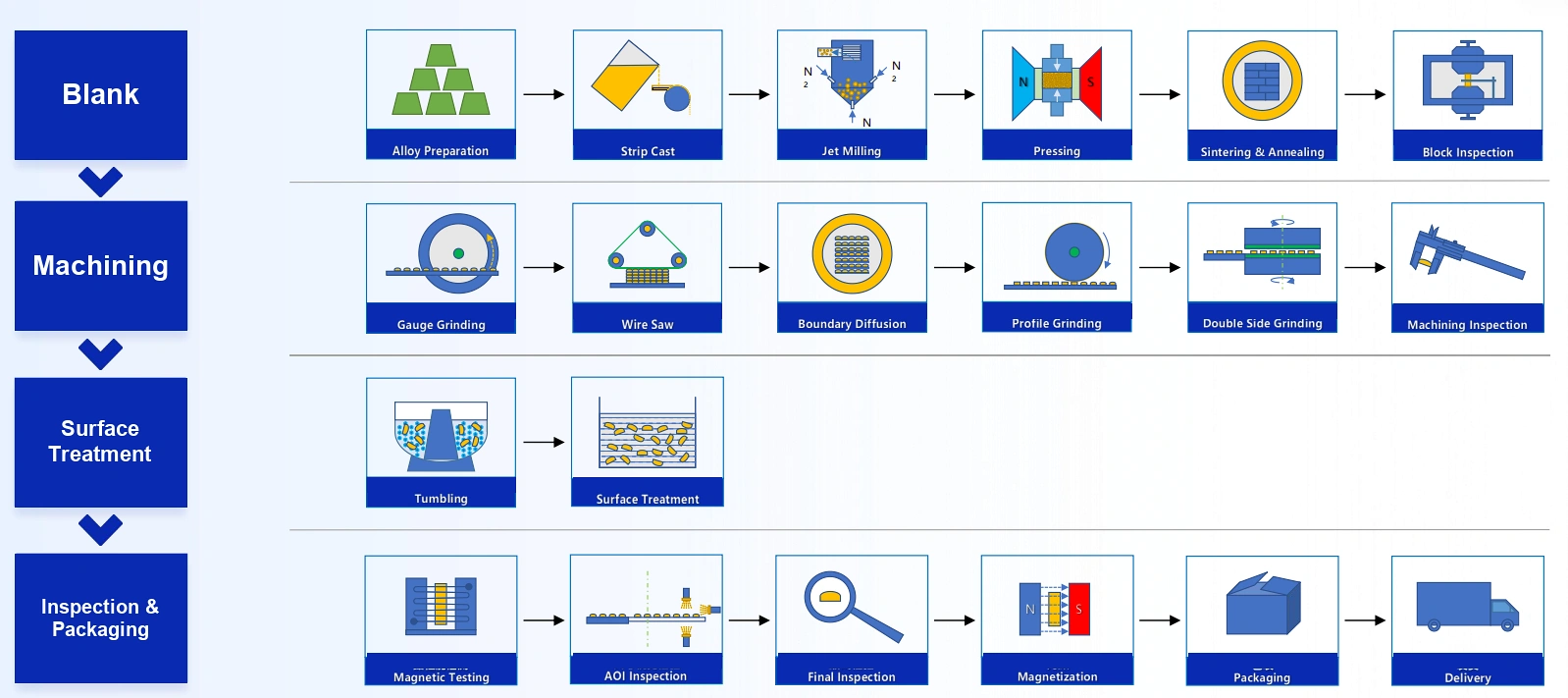
Process-Controlled Quality and Batch Consistency
Dimensional, magnetic and traceability controls are aligned with the approved drawing, inspection plan and sample-approval basis.
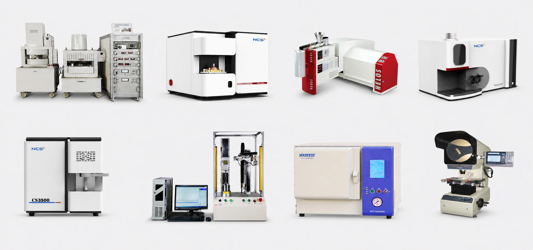
Control of Critical Arc-Segment Dimensions
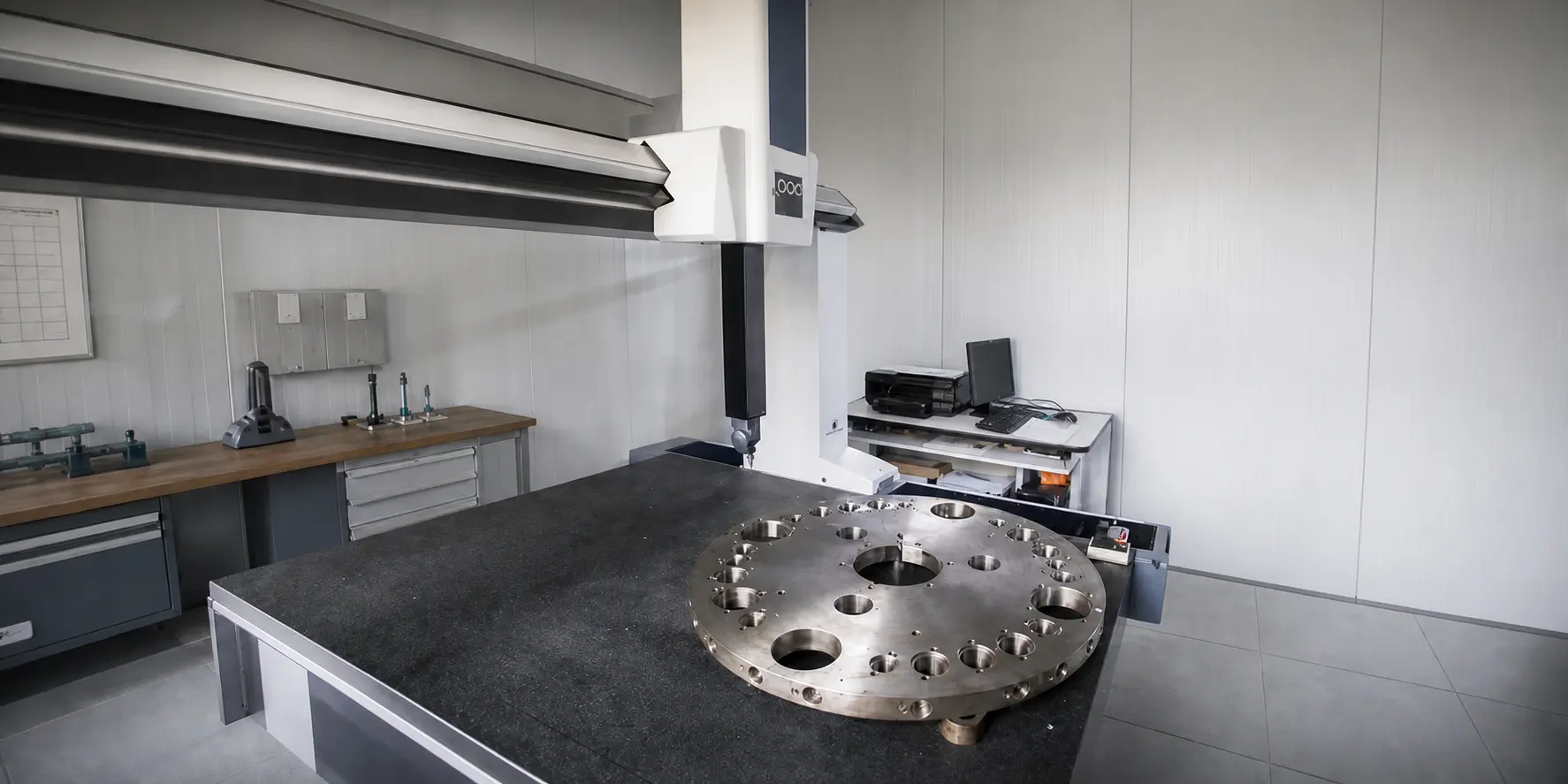
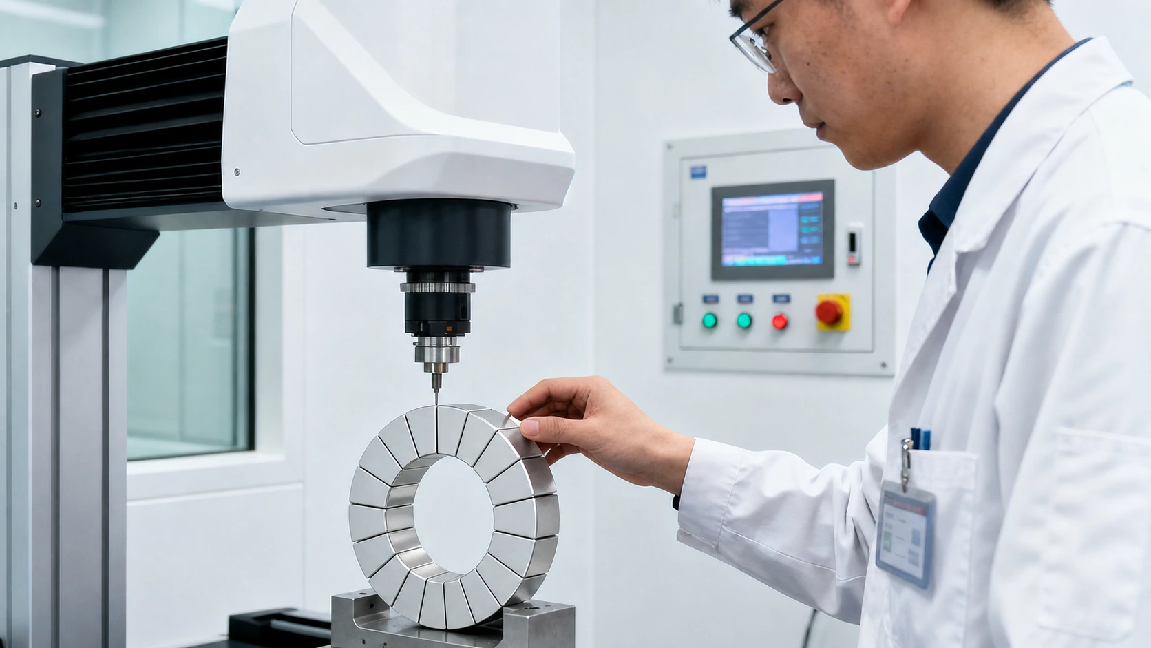
Critical dimensions—including the inner and outer radii, arc angle, axial length and edge profile—can be verified using coordinate measuring equipment and appropriate dimensional inspection methods. Combined with precision slicing and machining, these controls support conformity to the approved drawing, interchangeability within each batch and accurate full-circumference motor assembly.
Consistent Magnetic Output Across Production Batches
Batch controls address magnetic flux, magnetization direction and magnetization-angle variation according to the agreed inspection plan. Custom magnetization configurations are also available for project-specific pole arrangements. Consistent dimensional and magnetic characteristics help reduce motor variation associated with mismatched arc segments, including fluctuations in cogging torque, operating noise and output performance.
Process Traceability and Quality-System Support
Production and inspection records can link the relevant sintering, machining, coating and magnetization stages to the delivered batch. Applicable manufacturing sites operate under ISO 9001 quality-management controls, while automotive programs can be supported through IATF 16949-certified manufacturing resources where required. The relevant certificate holder, production site and project scope are confirmed for each program.
Application-Specific Material and Process Selection
GX reviews the operating environment and motor requirements before recommending the NdFeB grade, coating system and magnetization configuration. This helps align magnetic performance, corrosion protection and validation requirements with the actual application instead of relying on a general-purpose magnet specification.
Flexible Delivery Throughout the Project Lifecycle
GX supports the transition from drawing review and prototype validation to pilot builds and recurring production supply.
Prototype Support for Design Validation
Dedicated sampling resources and technical support are available for drawing-defined prototypes. GX can coordinate geometry review, material selection, magnetization requirements and sample preparation to support design verification and engineering iterations during development.
From Trial Orders to Batch Production
GX coordinates production across qualified manufacturing resources to support the transition from prototype quantities and pilot builds to recurring batch supply. The approved drawing, sample basis, inspection requirements and packaging specifications remain the reference throughout production handover.
Delivery Planning for Each Project Stage
Order quantities and delivery schedules can be aligned with the project stage—from engineering validation and pilot assembly to volume production. For automotive and other controlled programs, planning can also incorporate batch identification, traceability, packaging and project-specific quality documentation.
What Is an NdFeB Arc Magnet?
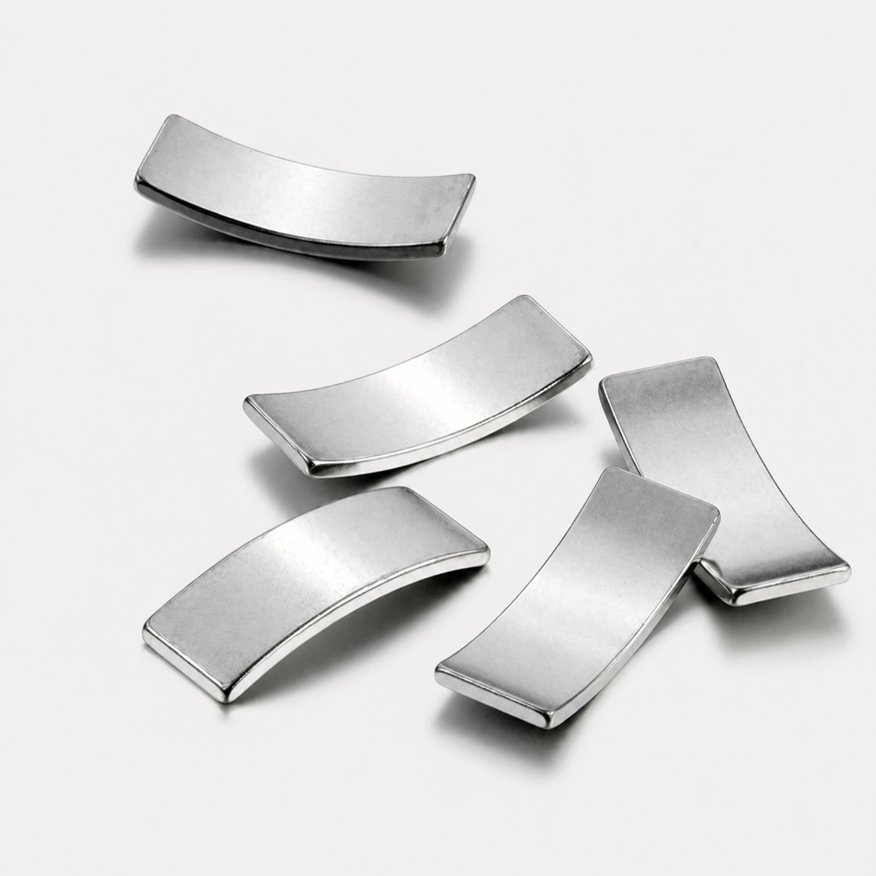
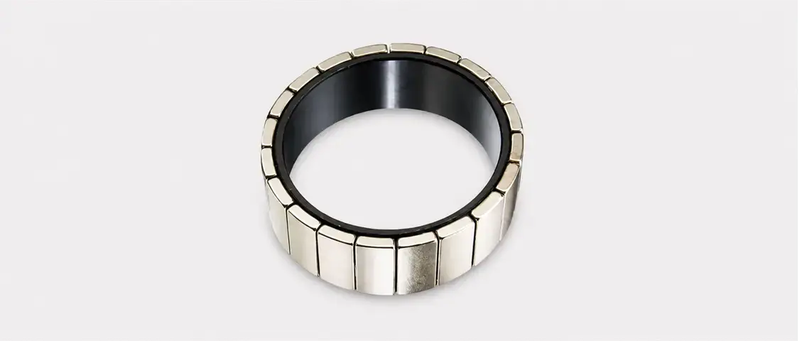
An NdFeB arc magnet, also known as a neodymium arc segment, is a curved permanent magnet made from sintered neodymium-iron-boron. Unlike a complete ring, it forms one defined sector of a circular magnetic assembly.
Curved Segment Geometry
An arc magnet is defined by its arc angle, inner radius, outer radius, radial thickness and axial length. Several matching segments may form part of a complete circular magnetic structure.
Magnetic-Circuit Inputs
The required material, magnetization direction, pole arrangement and working air gap should be evaluated with the motor or curved magnetic circuit, not as isolated magnet data.
Drawing-Based Project Scope
A customer drawing should identify the curved mounting surface, segment position, critical tolerances, operating conditions and validation requirements before sampling or production planning.

Selecting an NdFeB Arc MagnetConfiguration
| Category | Application | Purchasing Focus |
|---|---|---|
| Standard NdFeB Arc Segment Magnets | Permanent-magnet motor rotors, stators and circular magnetic assemblies. | Specification & Sizing Fit,Lot-to-Lot Quality Consistency |
| Skewed NdFeB Arc Segment Magnets | Motor projects using a drawing-defined skew arrangement around the rotor or stator. | Skew angle, segment alignment and magnetic requirement. |
| Custom-Profile NdFeB Arc Magnets | Curved magnetic circuits with non-standard arc geometry, mounting details or segment interfaces. | Drawing, mounting profile and validation scope. |
How Arc Magnets Work in Permanent-Magnet Motors
Arc Segments Follow the Motor Radius
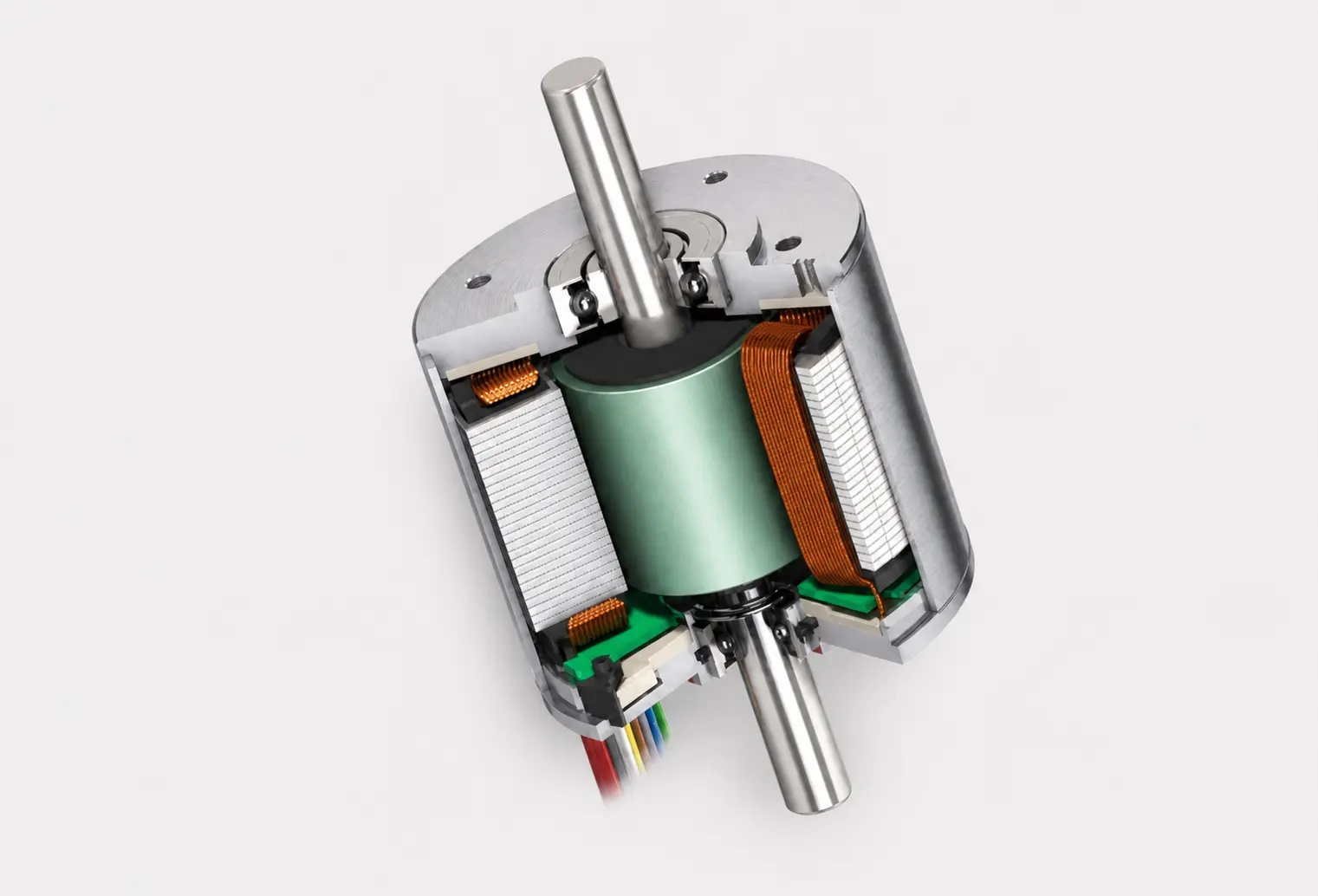
Individual arc magnets are positioned along the rotor or stator circumference so their curved surfaces match the motor’s circular geometry.
Magnetic Poles Form a Circular Field Pattern
The magnetization direction and pole arrangement establish the permanent magnetic field required by the motor design.
The Air Gap Provides Magnetic Coupling
Magnetic flux crosses the controlled air gap between the rotating and stationary parts of the motor, linking the rotor and stator magnetic circuits.
Stator Current Creates a Moving Field
Current in the stator windings produces a rotating magnetic field across the air gap.
Field Interaction Produces Torque
The permanent field from the NdFeB arc magnets interacts with the stator field to produce electromagnetic torque at the rotor.
Arc Geometry Supports the Final Motor Design
Arc angle, radius, radial thickness, axial length, pole layout and installation position are selected to match the intended motor structure and operating requirements.
Required Technical Inputs for NdFeB Arc Magnet Projects
Information needed to complete engineering review and formal quotation
| Parameter Category | Specification Variables | Information to Confirm |
|---|---|---|
| Arc Segment Geometry | Inner radius, outer radius, arc angle, radial thickness, axial length and drawing-defined edge profile. | 2D/3D drawing and critical dimensions |
| NdFeB Material Requirement | Sintered NdFeB material requirement evaluated against magnetic target, operating temperature and motor design. | Grade or magnetic target |
| Magnetization Configuration | Radial, axial or drawing-defined pole configuration reviewed for the intended curved magnetic circuit. | Direction, poles and polarity |
| Surface & Assembly Conditions | Surface condition, protection requirements, mounting method and operating environment reviewed for each project. | Environment and assembly details |
Arc Magnet Design Principles
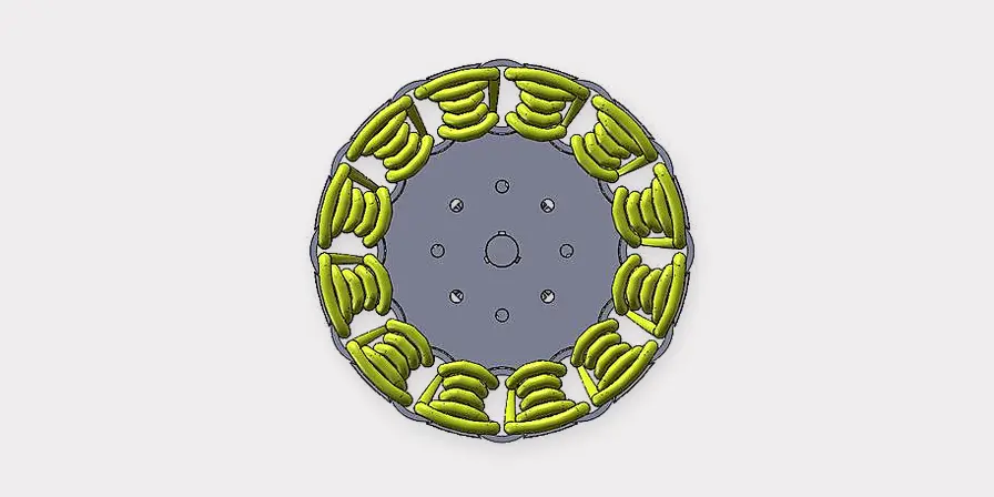
An NdFeB arc magnet is developed as part of a complete motor or curved magnetic circuit. GX reviews the following design factors with the customer drawing before defining the sampling scope.
Curvature MatchMatch the arc profile to the rotor or stator radius.
- - Define inner radius and outer radius
- - Confirm the curved mounting surface
Arc Angle & Segment CountEstablish how each arc segment forms the circular assembly.
- - Confirm arc angle per segment
- - Review quantity and circumferential spacing
Radial ThicknessSet the magnet wall thickness for the intended magnetic path.
- - Identify radial thickness requirements
- - Review available rotor space and air-gap relationship
Axial Length & Edge ProfileDefine the length and end details required by the assembly.
- - Confirm axial length and critical edges
- - Identify drawing-defined chamfers, steps or profiles
Magnetization DirectionAlign the magnetization direction with the motor design.
- - Specify radial, axial or another drawing-defined direction
- - Confirm polarity marking where required
Pole ArrangementReview the magnetic-pole structure as part of the complete rotor or stator.
- - Confirm pole sequence and segment position
- - Evaluate the required magnetic target with the circuit design
Retention & InstallationConsider how the arc magnet is located and retained in the final assembly.
- - Review bonding, sleeves, clips or drawing-defined retention features
- - Confirm installation direction and handling requirements
Operating & Validation ConditionsDefine the conditions used to approve the arc magnet project.
- - Share temperature, environment and duty-cycle inputs
- - Confirm validation methods and acceptance criteria
From Inquiry to Production Release for NdFeB Arc Magnets
GX Magnet follows a standardized review, sampling and production release workflow for every sintered NdFeB arc magnet project. All stages are strictly governed by the approved drawing and final project requirements.
| Project Stage | Inquiry & Technical Review | Sample Development & Validation | Production Release & Volume Supply |
|---|---|---|---|
| Primary Objective | Establish whether the arc segment geometry, magnetic requirement and motor interface can be defined for quotation. | Prepare and assess samples against the reviewed arc magnet specification. | Move the approved project into controlled batch planning and subsequent supply. |
| Key Project Inputs | Arc magnet drawing, motor application, material requirement, magnetization, critical dimensions and estimated demand. | Agreed drawing revision, sample quantity, acceptance criteria and assembly-validation feedback. | Approved sample basis, delivery requirements, packaging, identification and forecast information. |
| Project Output | A clarified review basis for quotation and the next technical step. | A sample-validation record supporting the final project specification. | A production-release basis for drawing-controlled NdFeB arc magnet supply. |

Engineering Review Deliverables
The engineering review converts the available motor and assembly inputs into defined project documents for quotation, sampling and production planning.
Interpret the Motor Requirement
Review the available motor drawing, rotor or stator interface, operating context and required magnetic function.
Output:
Define the Arc Magnet Interface
Assess arc angle, inner and outer radii, radial thickness, axial length, magnetization and critical fit references.
Output:
Support Sample Evaluation
Compare sample feedback, dimensional checks, magnetic requirements and assembly observations with the agreed project basis.
Output:
Need Help Defining Your Arc Magnet Specification?
Send GX your drawing, motor interface and magnetic requirements for a project review.
Manufacturing and Quality Control for NdFeB Arc Magnets
GX coordinates sintered NdFeB arc magnet production and quality verification against the approved drawing, project specification and sample-approval basis. Inspection focuses on curved geometry, magnetization, surface condition, identification and packaging.
Inspection Checklist
- Inner radius, outer radius, arc angle and radial thickness
- Axial length, edge profile and critical drawing dimensions
- Magnetization direction, pole arrangement and polarity marking where specified
- Appearance, surface condition, product identification and packaging requirements
| Problem | Possible Cause | Recommended Check |
|---|---|---|
| Arc segment fit variation in the rotor or curved carrier | A critical radius, arc angle, thickness or edge reference differs from the approved drawing. | Check curved geometry and critical dimensions against the drawing and the defined assembly reference. |
| Magnetization does not match the final motor assembly | Magnetization direction, pole arrangement or polarity identification requires confirmation against the project specification. | Verify the magnetization direction, pole arrangement and applicable magnetic checks against the approved sample basis. |
NdFeB Arc Magnet Applications
Sintered NdFeB arc magnets are typically specified where a curved permanent-magnet field must match a rotor, stator or circular magnetic path. Final suitability depends on the motor structure, air gap, magnetization layout and operating conditions.
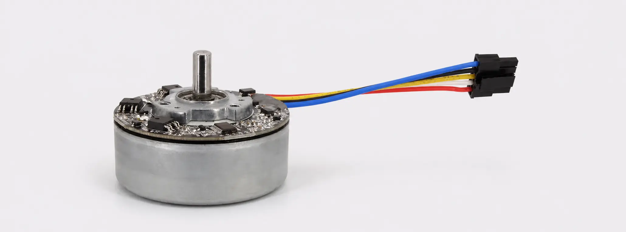
BLDC Fan & Blower Motors
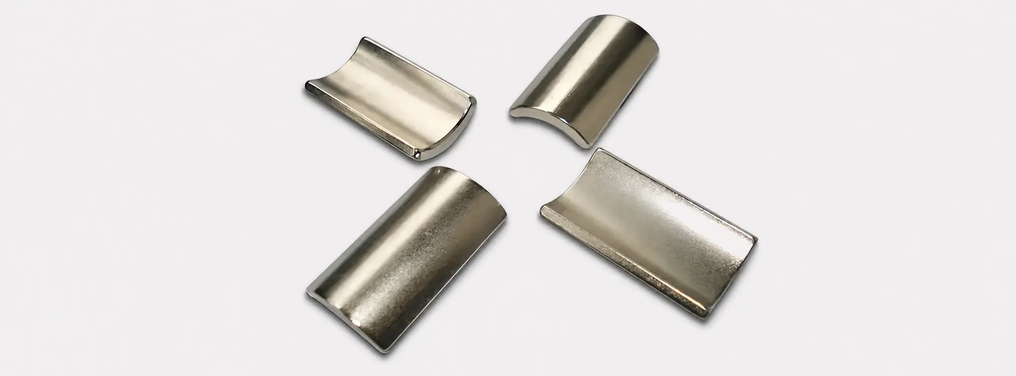
Automotive Auxiliary Motors
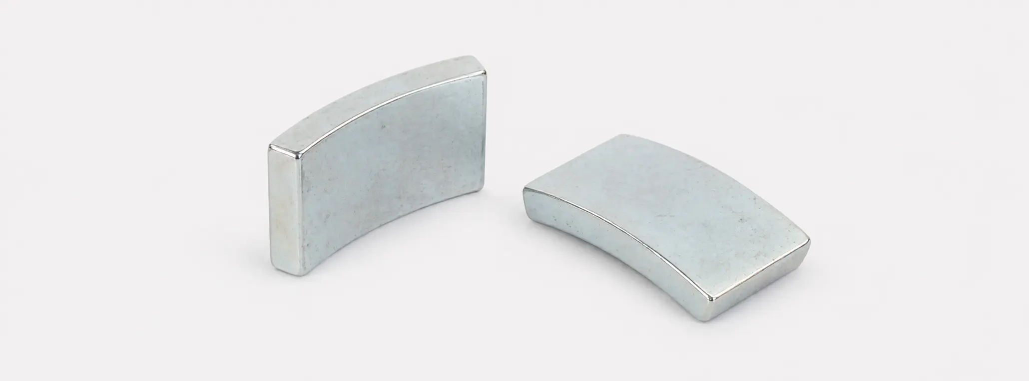
Home Appliance Drive Motors

Industrial Servo & Automation Motors
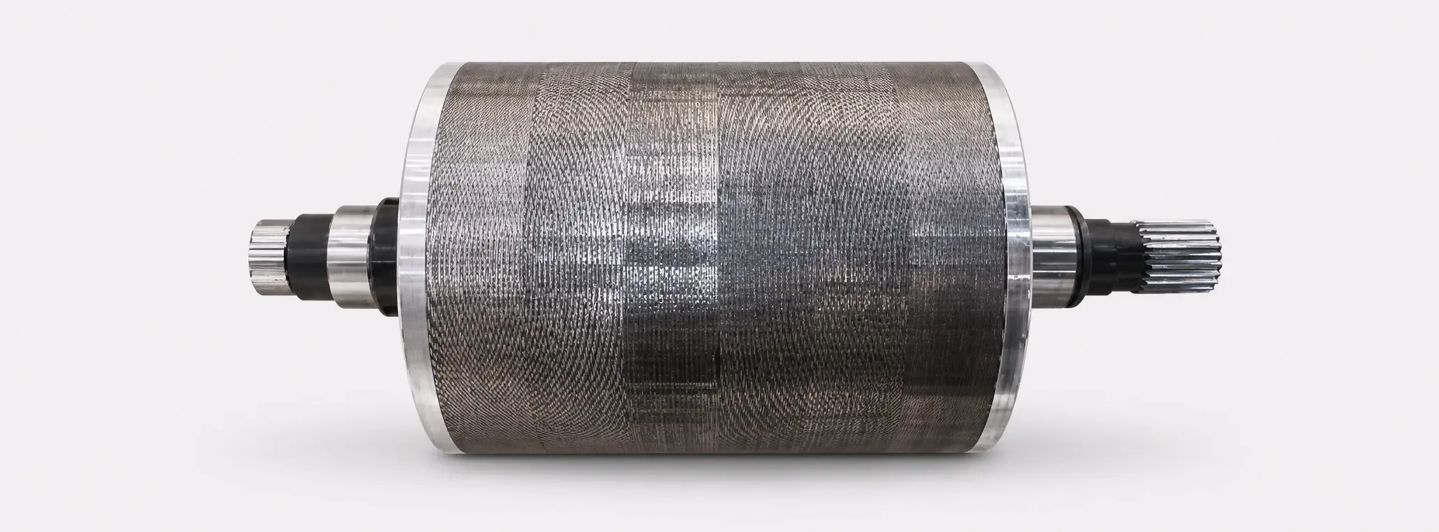
Electric Traction Motor Projects
Permanent-Magnet Generator Rotors
NdFeB Arc Magnet FAQs
What is the difference between an arc magnet and a ring magnet?
A ring magnet forms a complete annular shape with a central bore. An arc magnet is one curved sector; multiple segments may be arranged around a rotor, stator or other circular assembly.
What information is needed to quote an NdFeB arc magnet?
Please provide the available 2D or 3D drawing, inner and outer radii, arc angle, radial thickness, axial length, material requirement or magnetic target, magnetization details, application and estimated order quantity.
How is an arc magnet’s geometry specified?
The core geometry normally includes the inner radius, outer radius, arc angle, radial thickness and axial length. Edge details, chamfers, steps, locating features and critical tolerances should also be shown on the customer drawing where applicable.
What magnetization direction is used for motor arc magnets?
Radial magnetization is commonly used in curved motor magnetic circuits, but the required direction depends on the rotor or stator structure. Axial or other drawing-defined magnetization arrangements may also be reviewed for the project.
Can GX Magnet support custom NdFeB arc magnet profiles?
GX Magnet reviews drawing-defined sintered NdFeB arc magnets, including non-standard arc angles, radii, edge profiles and assembly interfaces. Final feasibility is confirmed through project review and sample requirements.
How is the NdFeB material requirement selected for an arc magnet?
The material grade should be selected against the magnetic target, operating temperature, air gap, motor design and application conditions. A grade designation alone does not determine performance in the installed magnetic circuit.
What is checked before NdFeB arc magnets are released for shipment?
Checks are defined by the approved drawing and project requirements. They may include critical curved geometry, magnetization or polarity requirements where specified, appearance, identification and packaging details.
How are NdFeB arc magnets used in permanent-magnet motors?
NdFeB arc magnets are installed along a rotor or stator circumference to establish a permanent magnetic field across the motor air gap. Their geometry, segment count, magnetization and installed position must match the motor’s magnetic-circuit design.
What is the maximum operating temperature of an NdFeB arc magnet?
The maximum operating temperature of an NdFeB arc magnet depends on its material grade, intrinsic coercivity (Hcj), geometry, permeance coefficient and the magnetic circuit in which it operates. Standard NdFeB grades are commonly used at temperatures around 80°C or below, while higher-coercivity grades can be selected for higher-temperature motor applications. The grade suffix alone should not be treated as a performance guarantee. Continuous and peak temperatures, reverse magnetic fields and the allowable irreversible flux loss should all be evaluated before the material is specified.
Do NdFeB arc magnets need a protective coating?
Most sintered NdFeB arc magnets require a protective coating because the base material is susceptible to oxidation and corrosion. Common surface treatments include Ni-Cu-Ni plating, zinc plating and epoxy coating. The appropriate coating depends on humidity, salt exposure, operating temperature, adhesive compatibility, dimensional tolerance and handling conditions. For bonded motor rotors or demanding environments, additional sealing or encapsulation may be required, particularly around edges where coating damage can create a corrosion path.
Let's Discuss Your Project
Contact our engineering and sales team for specification review, a project-specific quotation, or factory-audit coordination.