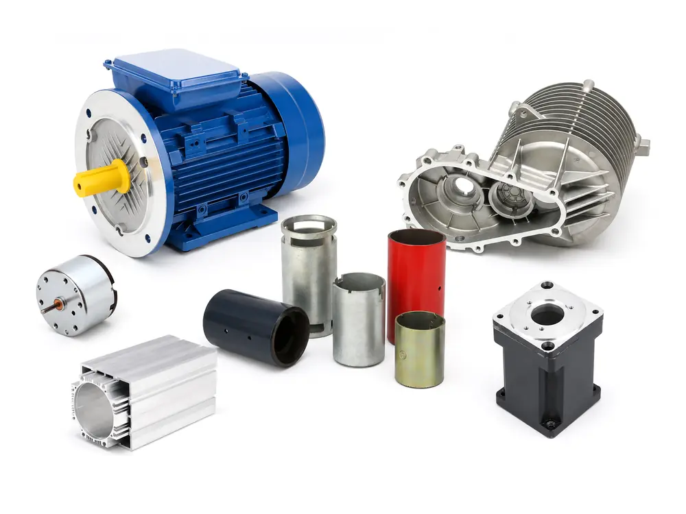
IEC Aluminum Frame
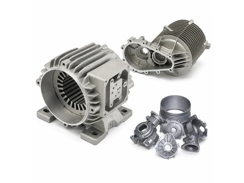
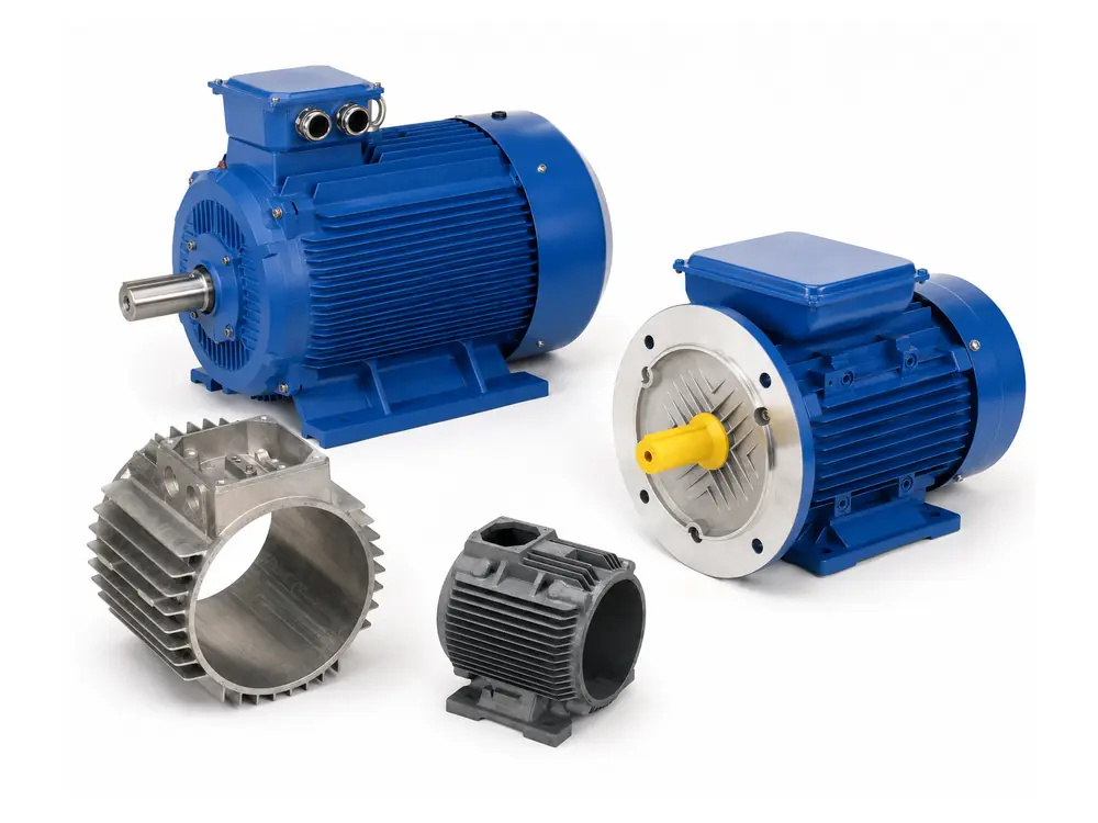
ADC12 or 6063-T5 reference for lightweight IEC-frame designs; B3, B5, B14 or B35 mounting, stator bore and end-cover pilots follow the released drawing.
DRAWING-BASED AC MOTOR HOUSING SUPPLY
Drawing-based AC motor housings for induction, inverter-duty, pump, fan and industrial drives, reviewed around IEC or NEMA frame requirements. Shaft height, stator bore, end-cover pilots, foot or flange mounting, cooling features and terminal-box interfaces are defined together before the manufacturing route is released.
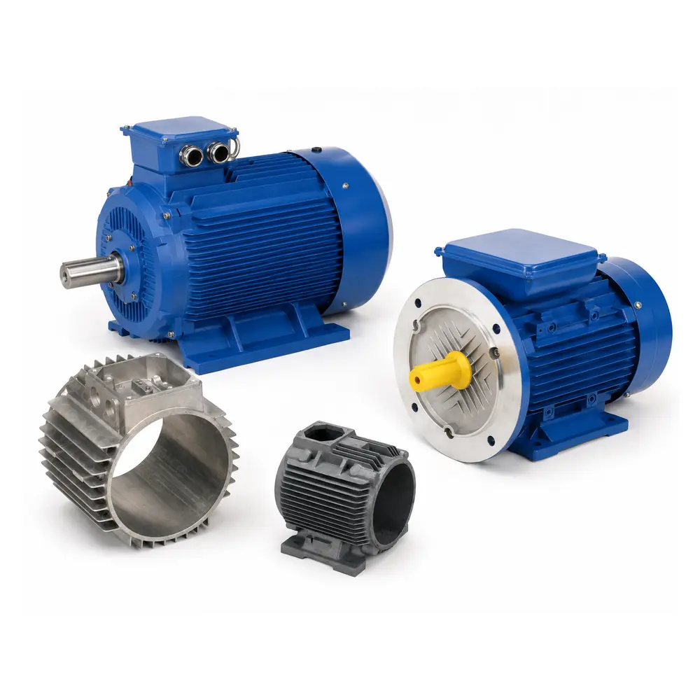










Product routes
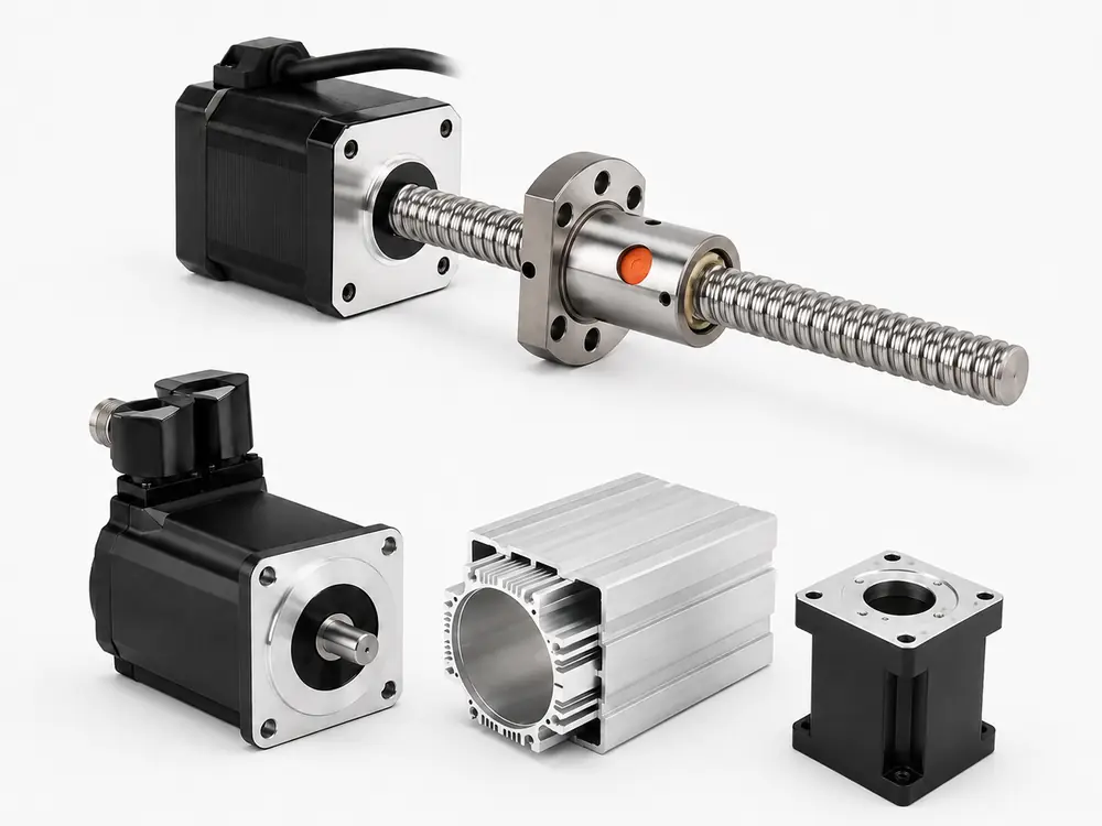
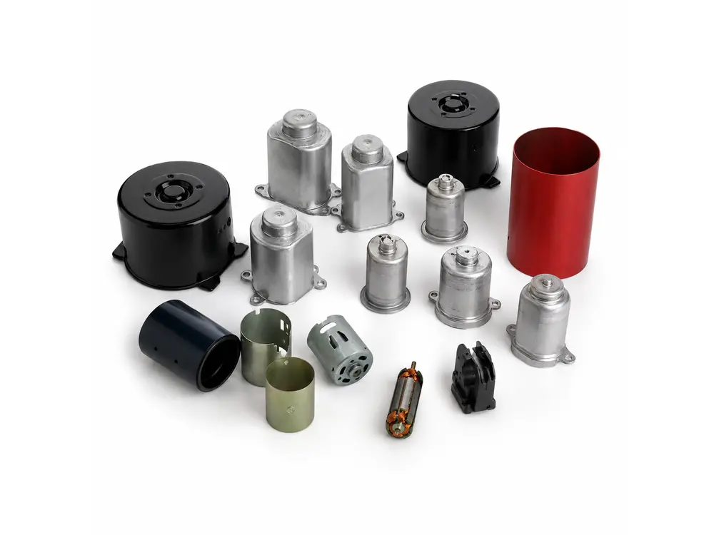
AC motor frames are selected around IEC or NEMA interfaces, mounting form, material, cooling method and operating environment. Final geometry and tolerances follow the released motor-interface drawing.
FOR A FASTER QUOTATION
Send the frame standard, drawing, mounting configuration, operating conditions and expected volume together. A complete RFQ package reduces clarification rounds and helps us review material, machining and inspection requirements at the same time.
Technical parameters for quotation
Use these parameters to align frame standard, mounting geometry, critical fits, cooling interfaces and inspection before quotation. Reference ranges support RFQ review; final requirements follow the released drawing and acceptance plan.
| Parameter group | Project-specific review basis | Release basis |
|---|---|---|
| Frame Standard / Material | IEC 56–400 or NEMA 42T–449T interface review; cast iron, aluminum or fabricated-steel route selected around size, load, thermal duty and volume. | Released frame standard, material specification and manufacturing route. |
| Mounting / Shaft Height | B3, B5, B14, B35 or drawing-specific mounting; shaft height, foot plane, flange pilot and mounting-hole pattern defined by the mating equipment. | Released mounting form, shaft height and interface drawing. |
| Stator / End-Cover Geometry | Stator bore and end-cover pilots may reference H7/H8 fits; coaxiality or TIR 0.03–0.10 mm where specified. | Released GD&T, datum scheme, fits and inspection method. |
| Cooling / Terminal Interfaces | Cooling fins, airflow path, terminal-box position, cable entry, drain points and grounding interfaces are reviewed around the motor package. | Released cooling, terminal-box and mechanical-interface requirements. |
| Surface / Environment | Specified machined surfaces may reference Ra 0.8–3.2 μm; coating, corrosion exposure and ingress interfaces follow project conditions. | Released finish specification, masking requirements and environmental criteria. |
| Inspection / Acceptance | Shaft-height measurement, CMM, bore/roundness, flange runout, foot geometry and coating checks selected by critical characteristic. | Approved sample baseline, inspection plan and defined acceptance limits. |
| Supply Boundary | Machined frame, coated housing or drawing-defined mechanical hardware/subassembly only when included in the quotation and BOM. | Released BOM and quoted supply scope. |
IEC / NEMA INTERFACE DEFINITION
AC motor housing design starts with frame size, shaft height, mounting form and the interfaces shared with the stator, end covers and driven equipment. GX reviews IEC 56–400 or NEMA 42T–449T frame requirements together with B3, B5, B14 or B35 mounting before the manufacturing route is released.

FRAME DATUM CONTROL
The machining route links the stator bore, end-cover pilots, foot mounting plane and flange interface instead of controlling them as isolated dimensions. Project references may include H7/H8 fits, 0.03–0.10 mm coaxiality or TIR and shaft-height tolerances around ±0.5 mm for IEC 56–132 or ±1.0 mm for IEC 160–400 where specified.

VERIFICATION BEFORE REPEAT SUPPLY
Final verification connects shaft height, stator bore, foot or flange mounting, end-cover pilots and cooling-related features to the released AC motor frame. Specified machined surfaces may be reviewed to Ra 0.8–3.2 μm, while IP23, IP55 or IP65 targets remain assembled-motor requirements rather than housing-only claims.
Final values apply to production only after confirmation in the released drawing, approved specification, quotation and acceptance plan.

Product and supply scope
An AC motor housing, or motor frame, supports and locates the stator and end covers while establishing the shaft height, mounting geometry and cooling path of the motor. For IEC or NEMA designs, foot or flange mounting, stator bore, end-cover pilots, cooling fins, terminal-box position and drain features must work as one mechanical package. Critical interfaces may use H7/H8 fits and 0.03–0.10 mm coaxiality or TIR where specified. GX supplies drawing-defined AC motor housings with the material, machining, surface finish and mechanical interfaces confirmed to the released drawing and BOM.
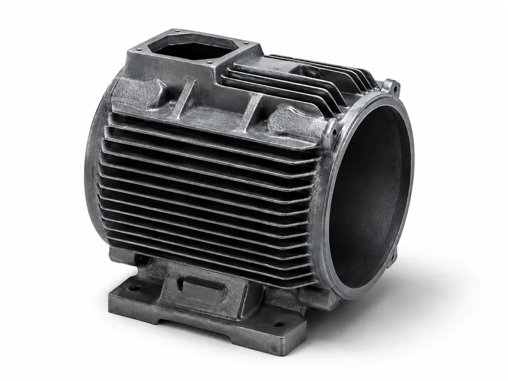
Project route
The manufacturing route links frame standard, material, shaft height, stator bore, foot or flange geometry and terminal-box interfaces through blank preparation, machining and surface finishing.

Confirm IEC or NEMA frame, mounting form, shaft height, stator bore, end-cover pilots and terminal-box orientation.
Select cast iron, aluminum casting, extrusion or fabricated steel around frame size, load, thermal duty and volume.
Produce the approved frame or blank with feet, flange, cooling ribs, bosses and required machining stock.
Remove flash, sand or residues and apply blasting, cleaning or stabilization where required before critical machining.
Machine the stator bore, end-cover pilots, foot plane, flange pilot and mounting faces from the released datum strategy.
Deburr, mask critical fits and apply coating while protecting machined, grounding and mating surfaces.
Verification
Verification ties shaft height, stator bore, end-cover pilots, foot or flange geometry and auxiliary interfaces to the same released IEC or NEMA frame definition.

| Control item | Method / evidence | Buyer benefit |
|---|---|---|
| Shaft Height / Mounting | Height gauge, CMM or dedicated frame fixture for shaft height, foot plane and mounting position. | Confirms the motor matches the required machine or base installation geometry. |
| Stator Bore / End-Cover Pilots | Bore gauge, roundness equipment and CMM for diameter, roundness, coaxiality or TIR where specified. | Controls air gap and bearing-axis alignmMaintains stator location and front-to-rear housing alignment.ent |
| Feet / Flange Geometry | Flatness, parallelism, perpendicularity, pilot and hole-position checks. | Reduces rocking, installation stress and coupling misalignment. |
| Cooling / Terminal Interfaces | Dimensional and visual checks for cooling fins, airflow openings, terminal-box position, cable entry and drain features. | Confirms auxiliary interfaces match the released motor package. |
| Surface / Protected Interfaces | Roughness, coating thickness and masking checks on machined, mating and grounding surfaces. | Protects fit, corrosion resistance and downstream assembly. |
Application fit
Application requirements are driven by mounting, load, cooling and environment—not by frame appearance alone.
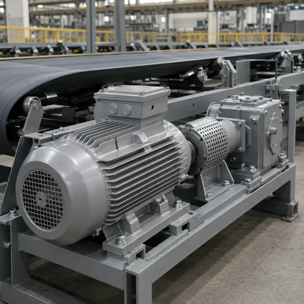
IEC or NEMA frames must maintain shaft height, stator alignment and foot or flange mounting under continuous industrial loads. H7/H8 fits can be reviewed where specified.
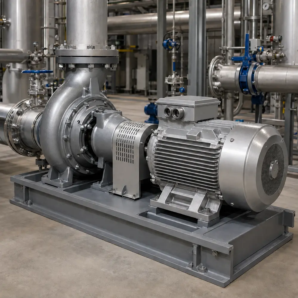
Bearing alignment, flange interfaces and sealing boundaries are critical around pumps and compressors. Coaxiality or TIR may be reviewed within 0.03–0.10 mm where specified.
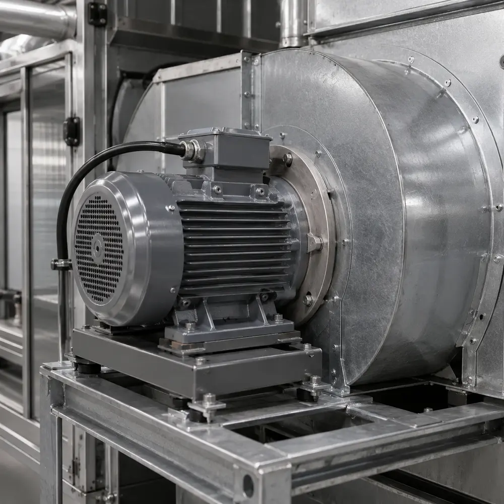
Cooling fins, airflow openings and terminal-box orientation must suit the installed airflow and service space while maintaining the required mounting geometry.
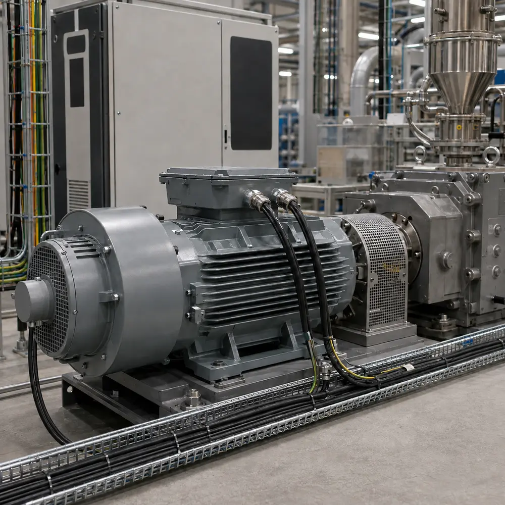
Variable-speed duty increases thermal and vibration demands on the frame. Cooling paths, mounting stiffness and critical machined surfaces can be reviewed to Ra 0.8–3.2 μm where specified.
Project control
GX maintains drawing revision, IEC or NEMA interface requirements, material and process controls, sample approval and critical-characteristic records against the agreed project scope. Certification claims apply only to the documented company, process and product scope.
Housing material, frame standard, shaft height, mounting form, cooling and terminal-box interfaces, supplied components and acceptance criteria follow the current released drawing and BOM.
Shaft height, stator-bore fit, foot or flange geometry, end-cover interfaces and project-specific checks are recorded to establish the approved production baseline.
Defined gauges, fixtures, inspection frequency and acceptance limits are carried into recurring production. Where process capability is specified, Cpk ≥1.33 can be used as the reference target for defined critical characteristics.
Project evidence is defined during quotation and may include material records, shaft-height results, dimensional or CMM reports, stator-bore geometry, flange or foot inspection, surface roughness, coating and marked-drawing records.
Buyer communication
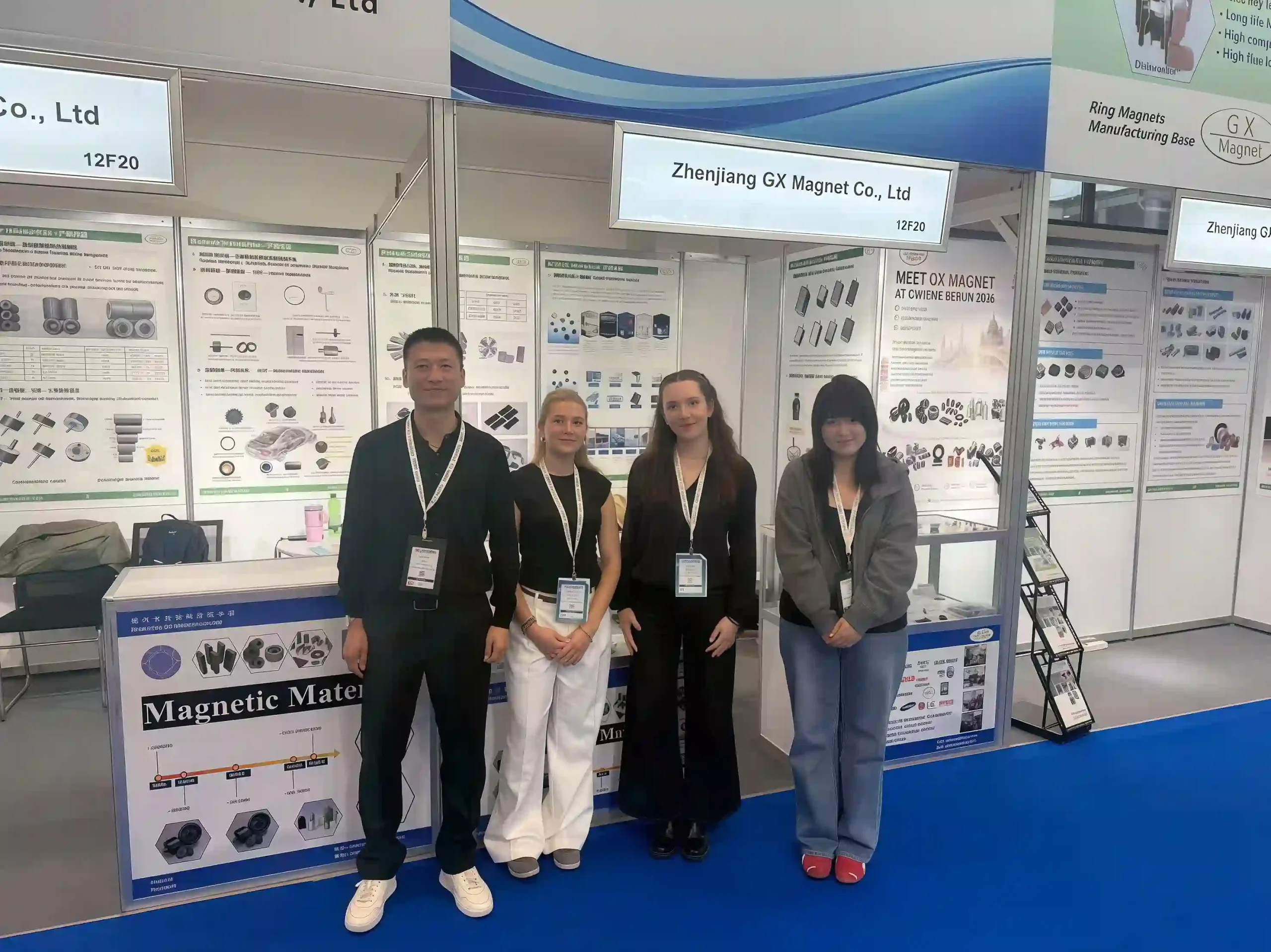
GX Magnet meets OEM buyers and engineers at industrial exhibitions to review AC motor housing drawings, IEC or NEMA frame requirements and mating interfaces. Face-to-face discussion helps clarify shaft height, mounting form, cooling, terminal-box position and missing RFQ details before quotation or tooling is finalized.
Compare matReview IEC or NEMA frame size, shaft height, B3/B5/B14/B35 mounting and drawing-defined interfaces.erials, housing forms, machined interfaces and surface treatments.
Align stator bore, end-cover pilots, feet or flange, cooling path and terminal-box configuration with the mating motor package.
Align DFM, sample approval, inspection evidence, change control and recurring-order requirements before project release.
Engineering and sourcing FAQ
Eight practical questions covering IEC/NEMA frame selection, shaft height, mounting form, stator and end-cover interfaces, cooling, inspection and repeat production.
The difference is determined by motor architecture, load path, bearing arrangement, cooling and manufacturing route. Compare the drawing interfaces and validation requirements rather than choosing by frame appearance alone.
Review cast or extruded material route, frame size and cooling requirement. The selected route must support the required datum structure, machining access, thermal behavior, surface treatment and projected volume.
The critical dimensions are those controlling rotor-stator alignment and final assembly. Typical review points include bearing bores, foot or flange datums, concentricity, fin geometry and terminal interfaces, but the customer drawing must identify the functional datum scheme and inspection priority.
Control them from a consistent machining datum and verify the relationship, not only each size independently. The acceptance plan should define bore size, position or concentricity, face runout and the gauge or CMM method.
Testing is required when the housing forms a sealed cavity, coolant path or specified environmental barrier. Define coating, sealing, leakage criteria, corrosion environment and inverter-duty thermal load, test pressure or method, allowable leakage and the surfaces included in the test boundary.
Inspection should combine material or casting checks with critical machined dimensions, datum relationships, thread and surface-condition checks. Coating thickness, cleanliness, leakage or packaging controls are added only when the released specification requires them.
Provide 2D drawings and 3D data, material and process preference, bearing bores, foot or flange datums, concentricity, fin geometry and terminal interfaces, coating, sealing, leakage criteria, corrosion environment and inverter-duty thermal load, annual quantity and acceptance method. Identify supplied inserts, machining scope, surface treatment and any required test fixtures.
Agree the drawing revision, datum strategy, critical-characteristic list and inspection method before production approval. The first-article package should record results and approved deviations; recurring supply follows the released drawing, quotation and control plan.
Request for quotation
Send 2D/3D files, mating interfaces, material and process requirements, operating limits, surface finish, sample quantity, annual demand and validation expectations.