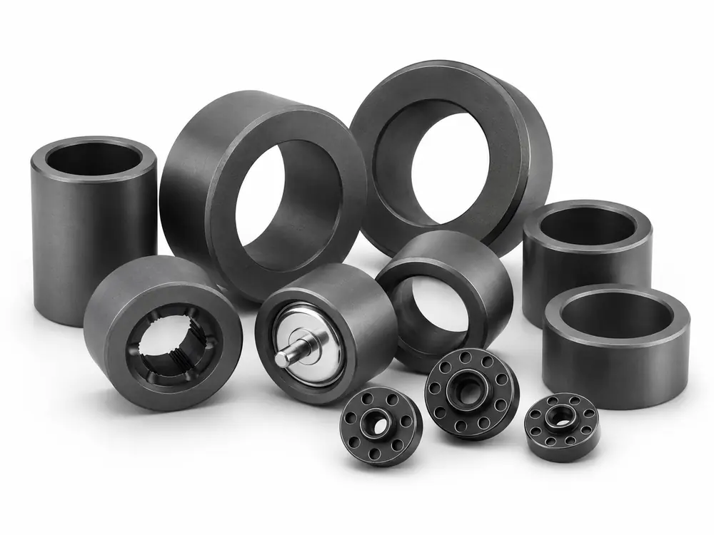
Rotor Supply Routes
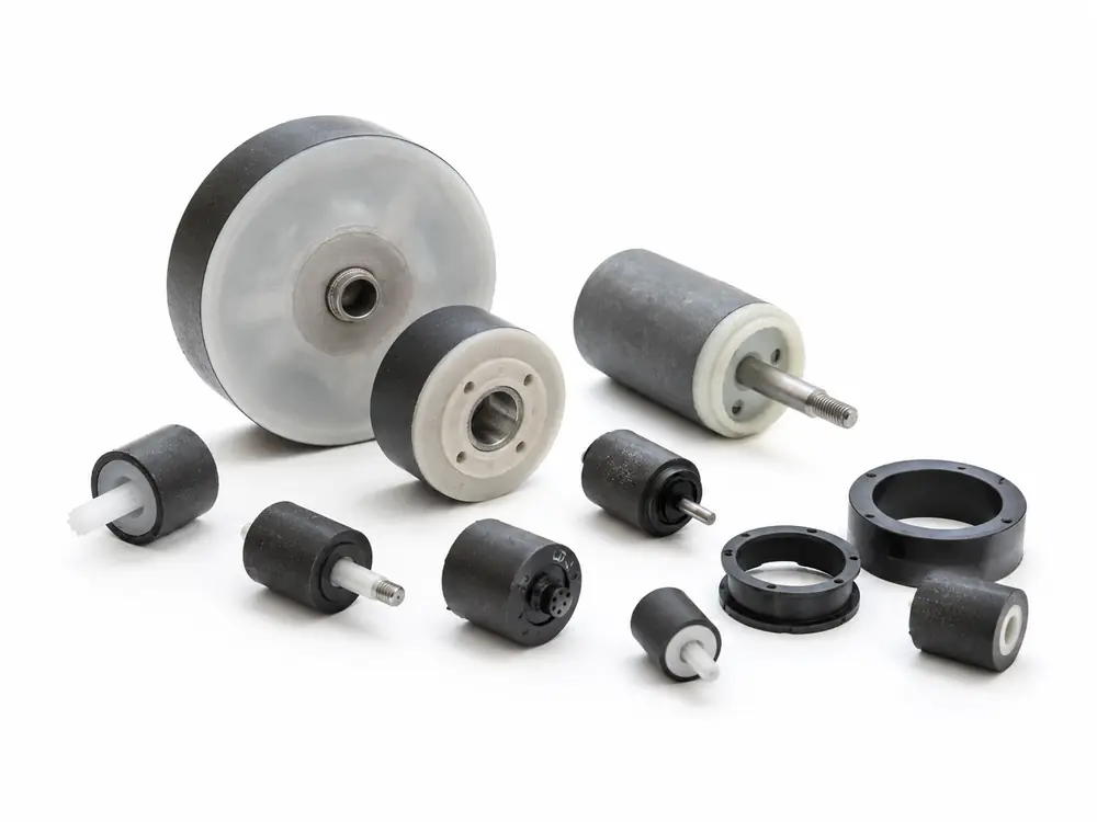
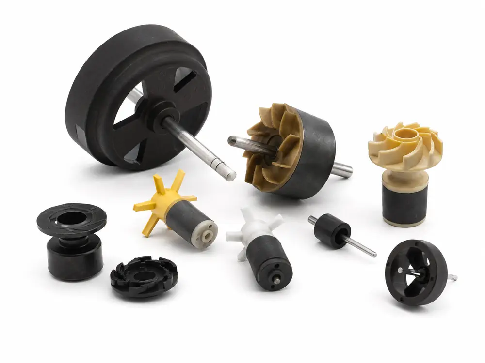
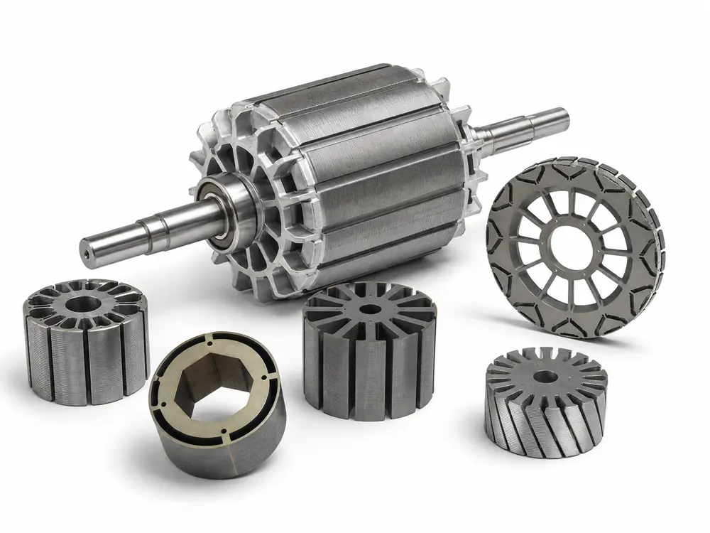
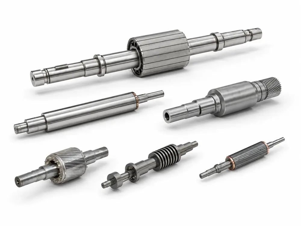
4 product routes — permanent-magnet rotor, bonded-magnet rotor, motor rotor assembly and rotor shaft assembly.
Motor Rotor · Drawing-Based Customization
GX Magnet evaluates custom inner-rotor and outer-rotor projects from drawings, combining the required magnetic material, rotor architecture, shaft or hub interface, retention or encapsulation route, magnetization and inspection plan.
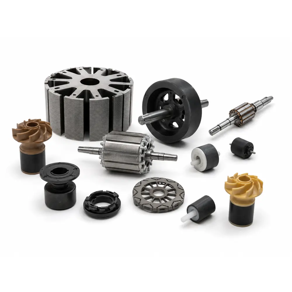
Drawing variables
The custom route connects magnetic function, mechanical architecture, retention, manufacturing and validation before tooling.
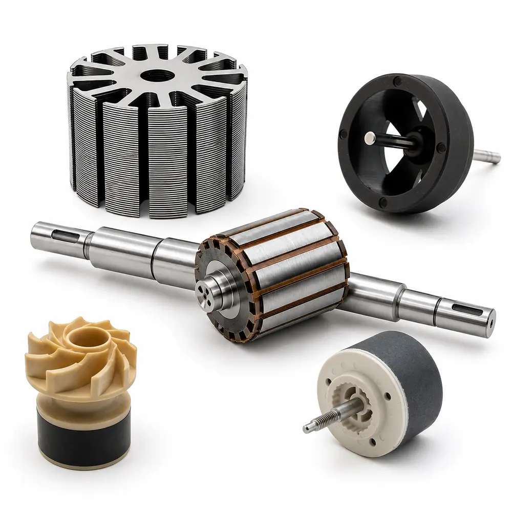
Engineering data
The specification is confirmed from the motor topology, magnetic target, drawings, mating stator, interfaces, retention route, operating conditions and validation plan.
| Parameter | Specification / Review Basis |
|---|---|
| Rotor Type / Supply Scope | 4 product routes — permanent-magnet rotor, bonded-magnet rotor, motor rotor assembly and rotor shaft assembly; inner/outer, reluctance and squirrel-cage structures reviewed by project. |
| Component Materials | Ferrite Y25–Y40 · NdFeB N35–N55 grade families · bonded Br 0.20–0.78 T · electrical steel · aluminum/copper cage · steel/stainless shaft · PA66/PPS inserts — selected by topology. |
| Dimensions / Fits | OD Ø8–200 mm · ID Ø2–100 mm · length 5–300 mm · shaft Ø2–50 mm · IT5–IT9 — final envelope and mating fits follow the approved drawings. |
| Magnetic / Functional | PM route: 2–64 poles · 50–500 mT · pole position ±1°–±3°; cage/reluctance route: stack, slot/bar/end-ring or flux-path criteria — method is rotor-specific. |
| Geometric Accuracy | Concentricity 0.005–0.15 mm · TIR 0.01–0.20 mm · straightness 0.01–0.10 mm/100 mm · Ra 0.2–3.2 μm — controlled from the rotational datum chain. |
| Mechanical / Rotational | Retention 30–5,000 N · torque 0.05–150 N·m · G0.4–G6.3 · rated ≤20,000 rpm · maximum ≤30,000 rpm — validation depends on the selected route. |
| Environment / Acceptance | −40 to 150°C · overspeed 1.2× · salt spray 24–240 h · AQL 0.65–1.5 — approved concept, drawings, BOM, sample and rotor-specific tests govern release. |
Typical review ranges across the four rotor product routes. Final values are not a single simultaneous specification and must be confirmed for the selected rotor type.
Project screening
Custom does not mean unspecified: the project still needs a controlled envelope, magnetic target, interfaces, operating conditions and acceptance method.
Product and supply scope
A custom motor rotor is developed around a specific motor topology, mating stator, air gap, magnetic target, shaft or hub interface and operating condition. The structure may use separate magnets, a magnetic ring, bonded material, sleeves, inserts or project-defined encapsulation.
GX reviews manufacturability and supply boundary from the customer drawing. Final materials, processes, tooling, included components, validation and recurring inspection are confirmed before quotation and sample release.
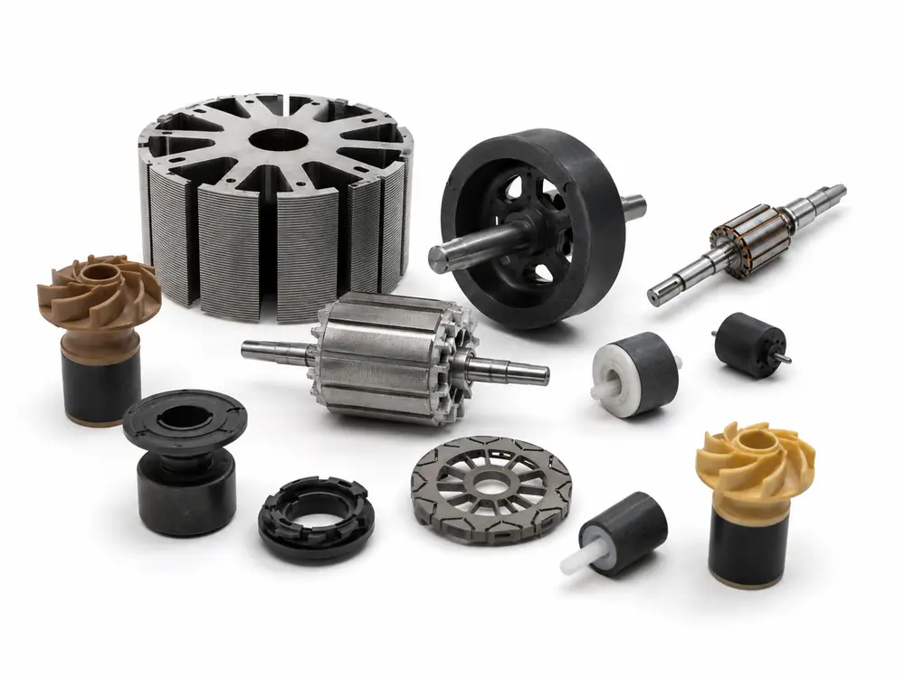
Project route
GX connects motor requirements, material choice, structure, tooling, assembly, magnetization and inspection to one approved project route.
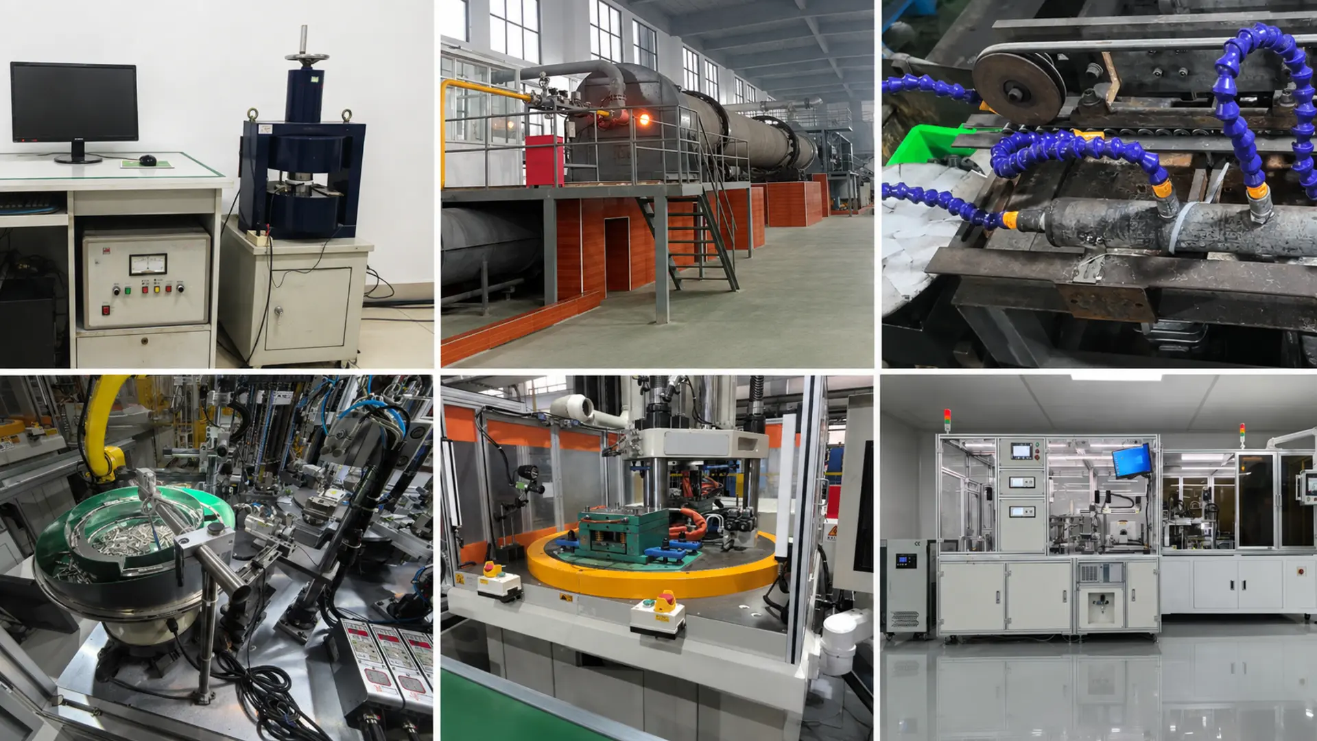
Drawings, motor topology, target, speed, environment and demand are checked.
Material, architecture, interfaces, retention and inspection risks are evaluated.
Fixtures, molds, joining route, datums and control points are defined.
Approved components and process settings are used for project samples.
Fit, magnetic response, runout, balance, retention and agreed tests are completed.
Approved drawing, sample, process window and inspection plan govern batches.
Verification
The control plan is selected from the rotor architecture, interfaces, magnetic system, speed, environment and buyer acceptance criteria.
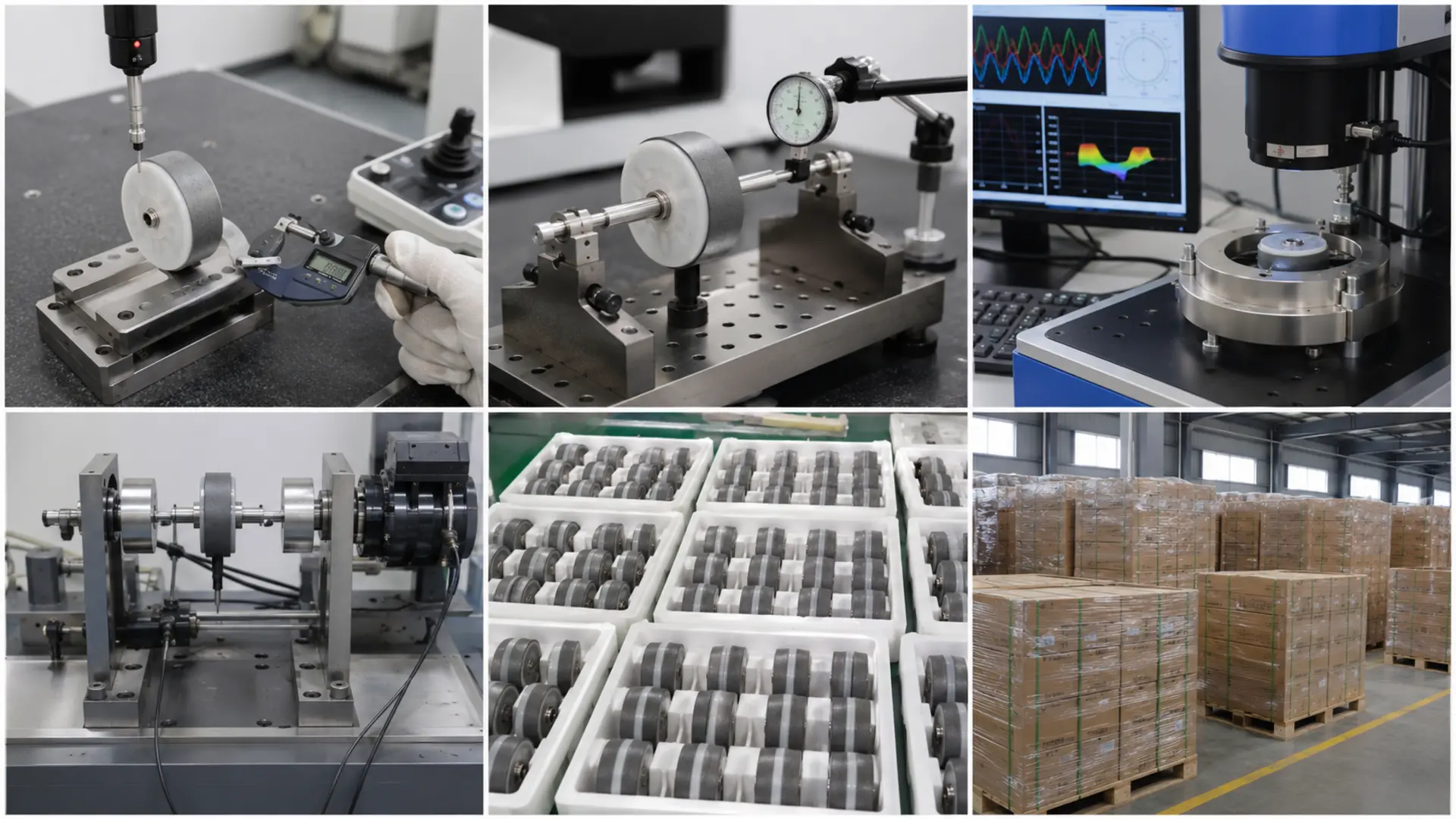
| Inspection item | Control approach | Why the buyer needs it |
|---|---|---|
| Critical dimensions | Envelope, datums, interfaces and air-gap surfaces checked | Controls fit and clearance |
| Concentricity / runout | Rotor surfaces evaluated against the approved rotation datum | Supports stable rotation |
| Magnetic result | Material property, pole pattern, waveform or function checked | Confirms the magnetic design |
| Retention / structure | Joints, sleeves, inserts or encapsulation evaluated as agreed | Reduces mechanical risk |
| Balance / appearance | Residual unbalance, edges, contamination and appearance checked | Supports acceptance and assembly |
Application fit
Custom rotor projects are evaluated where standard catalog geometry cannot satisfy the motor topology, interfaces, magnetic target or operating environment.
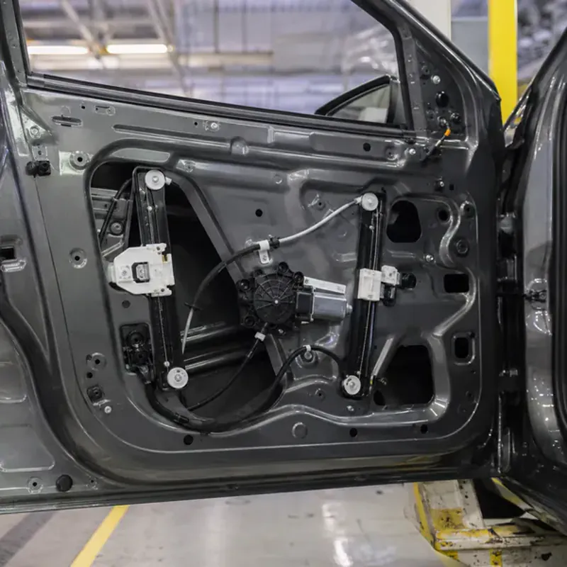
Compact geometry, temperature, speed, retention and production evidence are reviewed.
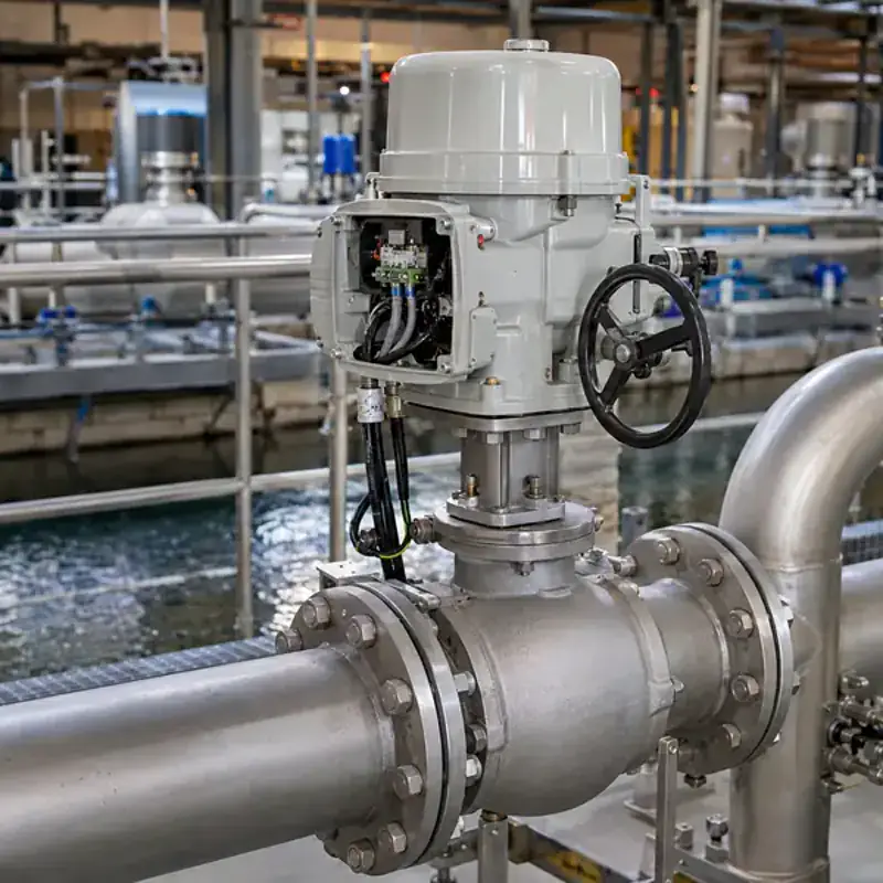
Moisture, fluid exposure, sealing interfaces, air gap and balance guide the design.
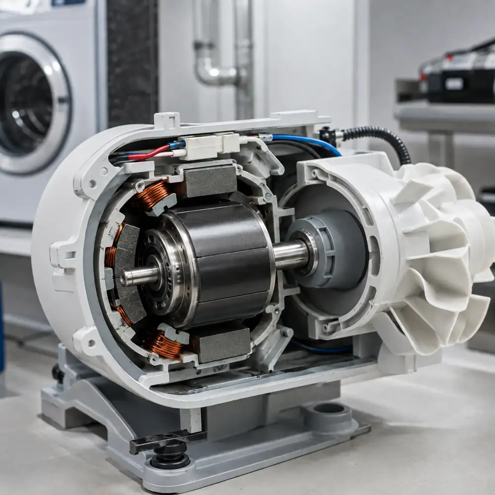
Noise, runout, magnetic consistency and recurring assembly requirements define acceptance.

Torque density, position control, shaft interfaces, speed and validation are project-specific.
Quality-system support
GX Magnet applies drawing revision, feasibility review, sample approval and project-defined inspection planning to custom rotor programs.
Magnet geometry, mechanical datums, pole layout, retention and appearance follow the approved drawing revision.
Prototype dimensions and agreed magnetic, fit, runout or balance checks are recorded before recurring production.
Inspection scope and sampling expectations are aligned before quotation and release.
Project-specific inspection records and magnetic performance data can be provided during sample approval or project review, based on the approved drawing and agreed acceptance criteria.

Buyer communication
GX Magnet uses industrial exhibitions to present magnetic materials, rotor assemblies and motor-component capabilities to OEM buyers, engineers and sourcing teams.
Bring the custom motor rotor drawing and mating-component information. The discussion can identify supply boundaries, interface risks and RFQ inputs before formal engineering review.
Compare magnet layouts, shaft or hub interfaces and rotor forms before choosing the quotation route.
Review air gap, speed, runout, balance, environment and validation expectations.
Plan drawing review, sample approval, inspection evidence and recurring communication.
GX Magnet
GX Magnet combines ferrite-material experience, magnetic-component capability and drawing-based rotor project support for automotive, appliance, pump, HVAC and industrial applications.
Magnet material, pole layout, rotor structure and retention are reviewed against the application.
Interfaces, samples and inspection criteria are controlled from approved revisions.
Engineering and sourcing teams receive a clear RFQ input list and project-specific supply boundary.







FAQ
Answers to the drawing, material, interface, validation and recurring-supply questions buyers normally resolve before approving a custom rotor source.
Use the custom route when topology, magnetic system, interfaces, retention, dimensions or validation cannot be defined by a standard component. GX first checks the drawing and supply boundary before confirming manufacturability.
Yes, subject to the rotor and mating-stator drawings, working air gap, magnetic target, speed, retention, runout, balance, environment and production-volume requirements.
Hard ferrite, sintered NdFeB, bonded ferrite and bonded NdFeB can be reviewed by project. Final selection depends on output, temperature, available volume, corrosion or fluid exposure, mechanical structure and cost.
GX can review drawing-based alternatives for material, rotor carrier, magnet arrangement, shaft or hub interface and retention. The motor target and constraints must be supplied; final design responsibility and approval remain defined by the project agreement.
Provide the mating drawings, insert materials, fits, sealing or overmold boundaries, torque and centrifugal loads, temperatures and chemical exposure. Tooling, shrinkage, retention and inspection are then reviewed together.
The approved drawing and pole map must establish rotational datums, magnetic position, air-gap surface and correction planes. Sample measurement methods and acceptance limits are agreed before recurring production.
GX needs an approved concept or drawing revision, material and component scope, critical dimensions, magnetic target, operating conditions, sample quantity and validation criteria. Open technical items should be resolved before tooling authorization.
Send 2D/3D drawings, motor topology, mating stator, magnetic target and pole map, shaft or hub interfaces, retention or encapsulation requirements, speed, balance, environment, validation plan and annual demand.
Request for quotation
Include the motor topology, drawings, mating stator, magnetic target, interfaces, retention route, speed, environment, validation and demand.