GX MAGNET Logo

Ferrite Magnet

Ferrite Bar Magnet Manufacturer

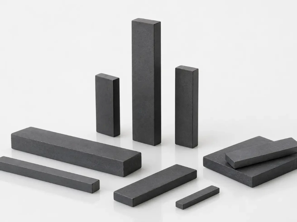
GX Magnet manufactures elongated sintered ferrite bar magnets to customer drawings for magnetic separation equipment, position-sensing and switching devices, holding fixtures and linear magnetic circuits. Length, cross-section, working faces, magnetization direction and finished-part magnetic output are reviewed together to match the assembly and operating requirements.

  • Long rectangular ferrite bars made to approved drawings
  • Length-to-section ratio, working faces and end details reviewed before tooling
  • Approved samples define dimensions, polarity, appearance and batch checks
Review Required Parameters
Supply statement: drawing-based sintered ferrite bar production
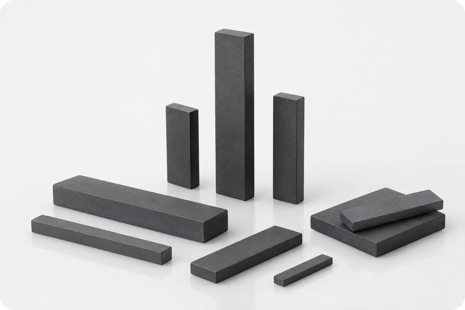
Ferrite bar magnet product family in multiple OEM lengths and cross-sections

Trusted Ferrite Manufacturing for Global Customer Programs

Bosch logo
Midea logo
Siemens logo
WEG logo
Gree logo
Shimge logo
Copreci logo
Buhler logo
Samsung logo
Nidec logo

RFQ INPUT CHECKLIST

Prepare a Complete Ferrite Bar Magnet RFQ

A complete drawing and specification package enables GX to select the pressing and magnetization route, assess tooling and inspection requirements, and prepare the quotation and sample plan on a consistent basis.

Drawing and Assembly InterfaceProvide the 2D or 3D drawing and revision, including length, width, thickness, straightness, flatness, chamfers, inspection datums and the bonding, sleeve or holder interface.
Material and Magnetic RequirementsSpecify the ferrite grade or magnetic target, isotropic or anisotropic orientation, working face and magnetization through the length, width or thickness. Define the required field, flux, pull force or switch response at the measurement position.
Application and Operating ConditionsState the application, working air gap, mating steel components, operating temperature, moisture, vibration, impact, contact medium and retention method.
Volume and Acceptance PlanConfirm sample quantity, annual demand and drawing revision, together with dimensional and appearance criteria, magnetic test method, fixture, sampling plan and required inspection records.

Why choose us for your project 

Ferrite Bar Geometry Built for Demanding Magnetic Separation Conditions

Elongated ferrite bars for magnetic‑rod assemblies face inherent challenges: warpage during sintering, performance drift under high‑temperature operation, and demagnetisation caused by adjacent‑magnet interaction.GX controls raw‑material formulation and full manufacturing workflow to deliver consistent magnetic output and reliable thermal stability. Every geometric feature is reviewed against real‑world service conditions within stainless‑steel magnetic rod housings.


Drawing-defined ferrite bar magnet lengths and rectangular cross-sections
Magnetic stability, thermal performance and geometry are validated as a complete solution for magnetic‑rod service.

Engineered around magnetic‑rod operating environment, rather than generic catalogue dimensions.

01

Geometry chain

Long ferrite bars are prone to sinter‑induced warpage, which creates uneven air‑gaps inside sleeves and weakens local magnetic force.GX applies controlled grinding process and strict straightness specification. Precise end‑face flatness enables gap‑free end‑to‑end splicing, eliminating magnetic dead zones along assembled magnetic rods.

02

Magnetic & Thermal Stability

Side‑by‑side installation brings mutual demagnetising effect; elevated processing temperature further challenges long‑term magnetic retention.Our optimised ferrite formula delivers stable magnetic performance within 3800‑4200 Gs together with high coercivity. Material maintains consistent output under sustained high‑temperature working conditions, resisting irreversible magnetic decay over service life.

03

Consistent supply for powder‑processing lines

Batch flux deviation, hidden internal cracks and edge chipping are common risks for elongated bar products, which may cause impurity leakage or powder contamination.GX implements full‑range inspection covering magnetism, internal structure and edge quality. Output is well‑suited for food, ceramic and lithium‑battery powder production with high cleanliness requirements.


Why choose us for your project 

Measurement & Validation Linked to Ferrite‑Bar Batch‑to‑Batch Consistency

Elongated ferrite bars face typical mass‑production risks: sinter warpage, flux deviation across batches, hidden internal defects and magnetic drift under high‑temperature operating conditions.GX leverages comprehensive in‑house metrology and magnetic‑testing instruments to lock in geometric accuracy, magnetic performance and thermal stability. Every production lot goes through defined validation before order dispatch.


Drawing-defined ferrite bar magnet lengths and rectangular cross-sections
Geometry, magnetic property and thermal reliability are fully validated for each production batch.
01

METROLOGY VERIFICATION

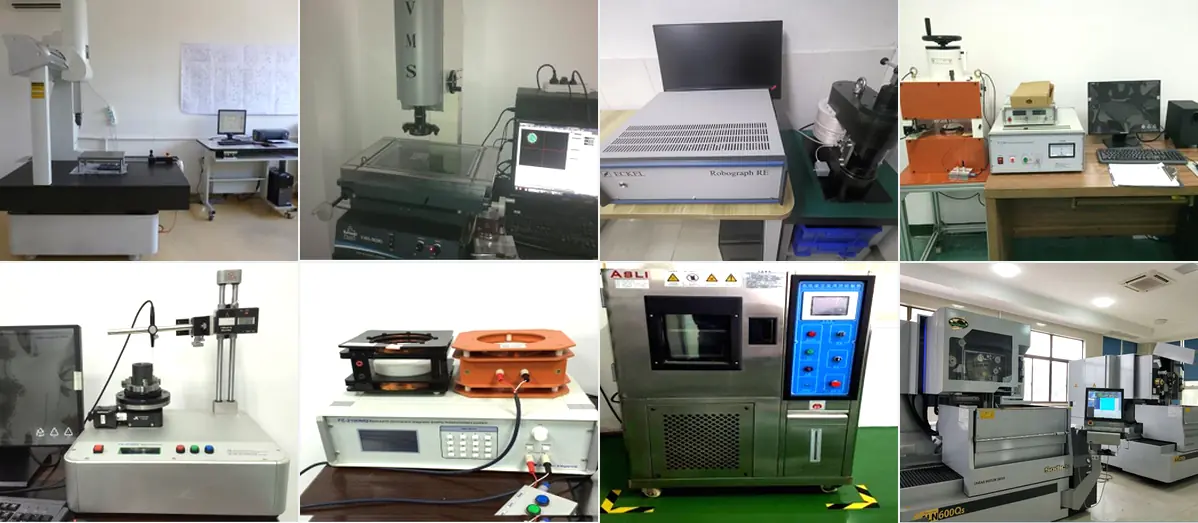
CMM, contourgraph and optical projector deliver high‑precision dimensional and form‑tolerance inspection, validating straightness, flatness and end‑face quality for every batch.

02

MAGNETIC PERFORMANCE TESTING

B‑H analyser, total flux tester and multi‑pole waveform tester confirm Br, Hcj, overall flux and magnetic uniformity, securing consistent magnetic output lot‑by‑lot.

03

RELIABILITY VALIDATION

High‑low‑temperature test chamber simulates actual service environment to evaluate thermal‑magnetic stability, confirming product fitness for customer end‑application before shipment.


Why choose us for your project 

One‑Person One‑Line Workflow Reduces Handling Damage

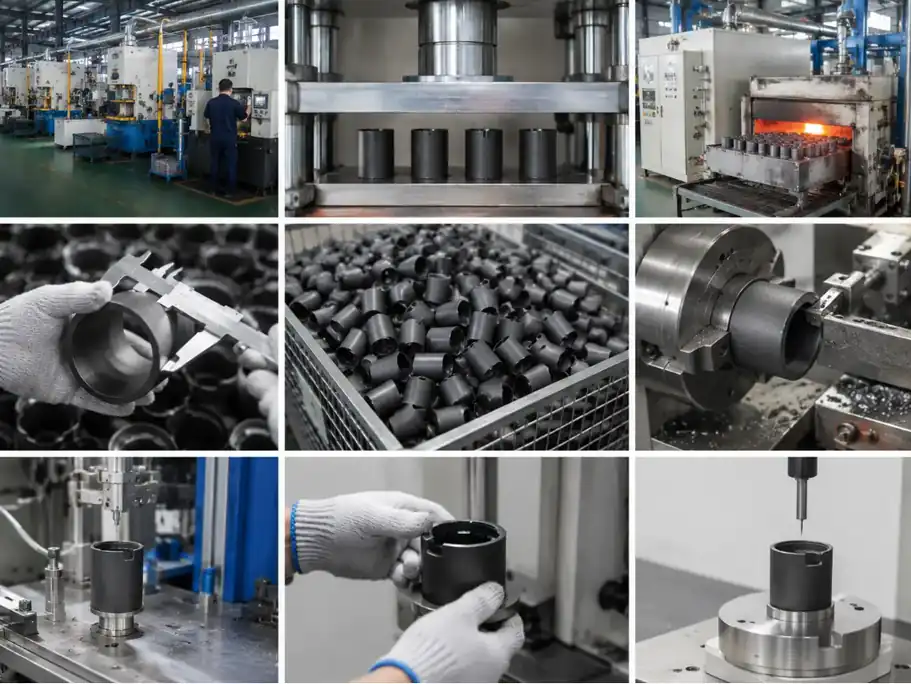
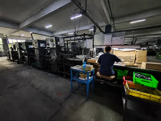
GX optimises ferrite bar grinding, cleaning and inspection into a continuous workflow. One operator manages a complete production line, reducing repeated manual transfer, part stacking and knock damage. This structure helps stabilise dimensional accuracy, edge quality and overall yield for elongated ferrite bars.

Ferrite bar magnet dimensional and functional magnetic validation
Continuous workflow minimises manual handling and supports consistent finished quality.
Workflow structureGrinding, high‑pressure water cleaning and inline inspection run on one continuous line, replacing traditional ultrasonic cleaning to lower energy consumption.
Magnetic responseElongated brittle ferrite bars complete full process inline. Less repeated manual transfer avoids collision and edge‑chipping damage.
Application boundaryInline inspection screens defective parts in real‑time. Most ferrite bar orders achieve production yield above 90%.
Recurring releaseInspection embedded into continuous production line requires high‑level equipment coordination and process control, demonstrating advanced manufacturing strength.

Process parameters and yield targets serve as supply commitments after drawing confirmation and production validation.

PRODUCT DEFINITION AND SUPPLY SCOPE

What Is a Ferrite Bar Magnet?

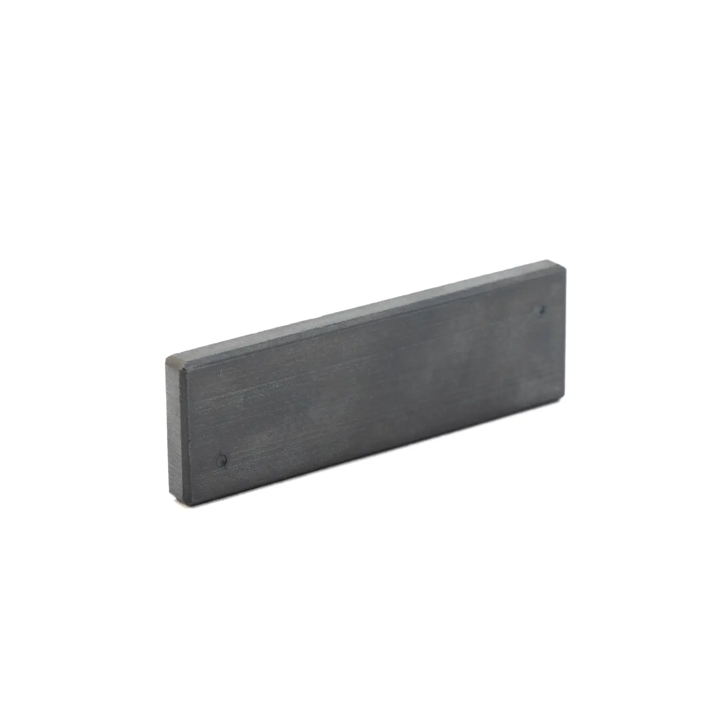
A ferrite bar magnet is an elongated rectangular or square permanent magnet produced by pressing and sintering hard-ferrite powder. Its extended pole face suits linear magnetic circuits used in holding, separating, sensing and actuation assemblies.

GX manufactures sintered strontium ferrite bars to customer drawings. Length, cross-section, straightness, working faces, edge condition, magnetic orientation and magnetization direction are reviewed with the required air gap and finished-part magnetic target before sampling.

Long ferrite bar magnet with flat working surfaces
Application and Circuit FitSelect the bar length, cross-section and working face to match the available installation space, mounting method and magnetic air gap.
Magnetic DefinitionSpecify isotropic or anisotropic material, magnetization through the length, width or thickness, polarity, and the required field, flux, pull force or switch response.
Sample and Production ApprovalDimensions, straightness, flatness, edge condition, polarity and magnetic response are verified against the approved drawing and sample before recurring production.
Defined Supply ScopeThe quotation identifies whether GX supplies the bar magnet only or also includes a sleeve, holder, back plate, adhesive or assembly.

TECHNICAL PARAMETERS FOR RFQ

Select Ferrite Bar Magnet Parameters for Your Application

Use the application and assembly conditions to define the material, cross-section, magnetization, interfaces and acceptance criteria. The approved drawing, specification, quotation and inspection plan then establish the requirements for sampling and recurring production.

Parameter groupProject-specific review basisConfirmation and Release Basis
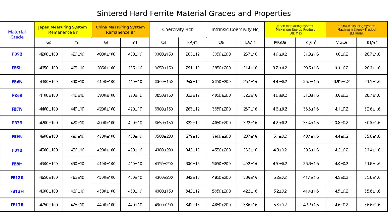
Material / routeSintered strontium ferrite; grade and isotropic or anisotropic orientation selected for the required field direction, operating temperature and magnetic circuit.Approved grade and orientation recorded in the released specification; Br, Hcb, Hcj and (BH)max report provided when specified.
Geometry and tolerancesLength, width, thickness, straightness, flatness, parallelism, working faces, chamfers and edge or chipping limits.Released drawing defines dimensions, datums and tolerances; first-article dimensional inspection confirms conformance.
Magnetic or functional requirementMagnetization through the length, width or thickness; required polarity and finished-part field, flux, pull force or switch response at a defined position or air gap.Approved sample report records the magnetic target, measurement position, air gap, fixture and test conditions.
Mechanical / assembly interfaceBonding, sleeve or holder interface; mating dimensions, locating datums, retention method and installed orientation.Assembly drawing confirms the interface and retention requirements; fit or retention testing is completed when specified.
Operating environmentOperating temperature, thermal shock or cycling, moisture, vibration, impact, contact medium and installation condition.Validation plan defines the applicable exposure conditions, test duration and acceptance criteria.
Inspection and acceptanceDimensional and visual inspection plus the agreed magnetic or functional test under defined measurement conditions.Control plan specifies the inspection method, gauge or fixture, sample size, frequency and lot-release records.
Supply boundaryBar magnet only, or a sleeve, holder or separator assembly when included in the quotation.Quotation and released drawing identify the supplied components and the included grinding, magnetization, inspection, packaging and documentation.

Assembly interface

Bonding, Mechanical Retention and Edge Protection

Sintered ferrite is hard and brittle. The assembly design must support the long bar without concentrating impact or bending load at one point.

Bonding Surface

Identify the bonding face, adhesive gap and surface condition. Do not assume the magnetic working face and bonding datum are interchangeable.

Mechanical Retention

Share clips, slots, back plates or holders so contact points and clearance can be reviewed against the brittle ceramic body.

Assembly Load

Avoid press-fit, point impact and forced bending unless the project has a validated fixture and acceptance method.

Pressing Direction

Cross-section, magnetic orientation and pressing direction are reviewed together because density distribution and the required pole faces cannot be separated.

Sintering Shrinkage

Length-to-section ratio affects shrinkage and deformation risk. Straightness and end condition must be tied to an agreed datum and measurement setup.

Grinding Support

Only functionally necessary faces should receive tight finishing controls. Long bars require stable support so grinding does not introduce bending load or edge damage.

Chips and Fragile Ends

Chamfers, allowable chip zones and critical ends are agreed from the assembly interface; zero visual chipping cannot be assumed for every brittle ferrite geometry.

Inspection and validation

Inspection Points Specific to Ferrite Bar Magnets

The inspection and delivery plan separates geometry, working surfaces, magnetic acceptance, edge condition and transport protection so production is not released from a generic magnet specification.

Drawing-to-sample-to-batch control points
Control areaWhat is reviewedWhy it matters
Overall geometryLength, width, thickness, squareness, radii and drawing datumsSupports assembly fit and repeatable positioning
Working surfacesFlatness, parallelism, ground faces and bonding interfaces where specifiedControls the installed air gap and contact condition
Magnetic propertiesMaterial or agreed magnetic target under a defined methodConnects the bar to the customer magnetic circuit
PolarityMagnetization direction and north/south face identificationPrevents reversed installation or incorrect field direction
Edges and appearanceChamfers, chips, cracks, surface condition and agreed acceptance limitsReduces handling and assembly risk for brittle ferrite
Packaging interfacePart separation, supported spans, end protection, layer control and orientation marking where agreedProtects brittle edges, working faces and long sections during export transport and unpacking

Drawing control

Revision, datums, critical faces and special features remain traceable.

Sample control

Dimensions, magnetization, magnetic acceptance and appearance are approved before release.

Batch control

Recurring orders follow the released drawing, approved sample and agreed checks.

Geometry-led applications

Where Ferrite Bar Geometry May Fit an Assembly

Ferrite bar or rod geometry is useful when a mechanism needs an elongated magnetic body, defined pole locations, linear travel beside a sensor, or several magnetic elements arranged across a wide capture area. Final suitability still depends on the magnetic circuit, dimensions and magnetization specified for the assembly.

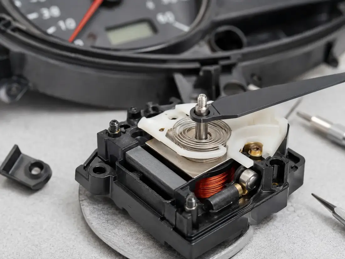
Ferrite bar or rod magnet inside an analog instrument pointer drive mechanism

Instrument Pointer Drives

Match the bar length, cross-section, pole orientation and installed position to the coil or armature. Sample approval verifies mounting fit, pointer movement and the drawing-defined magnetic response.

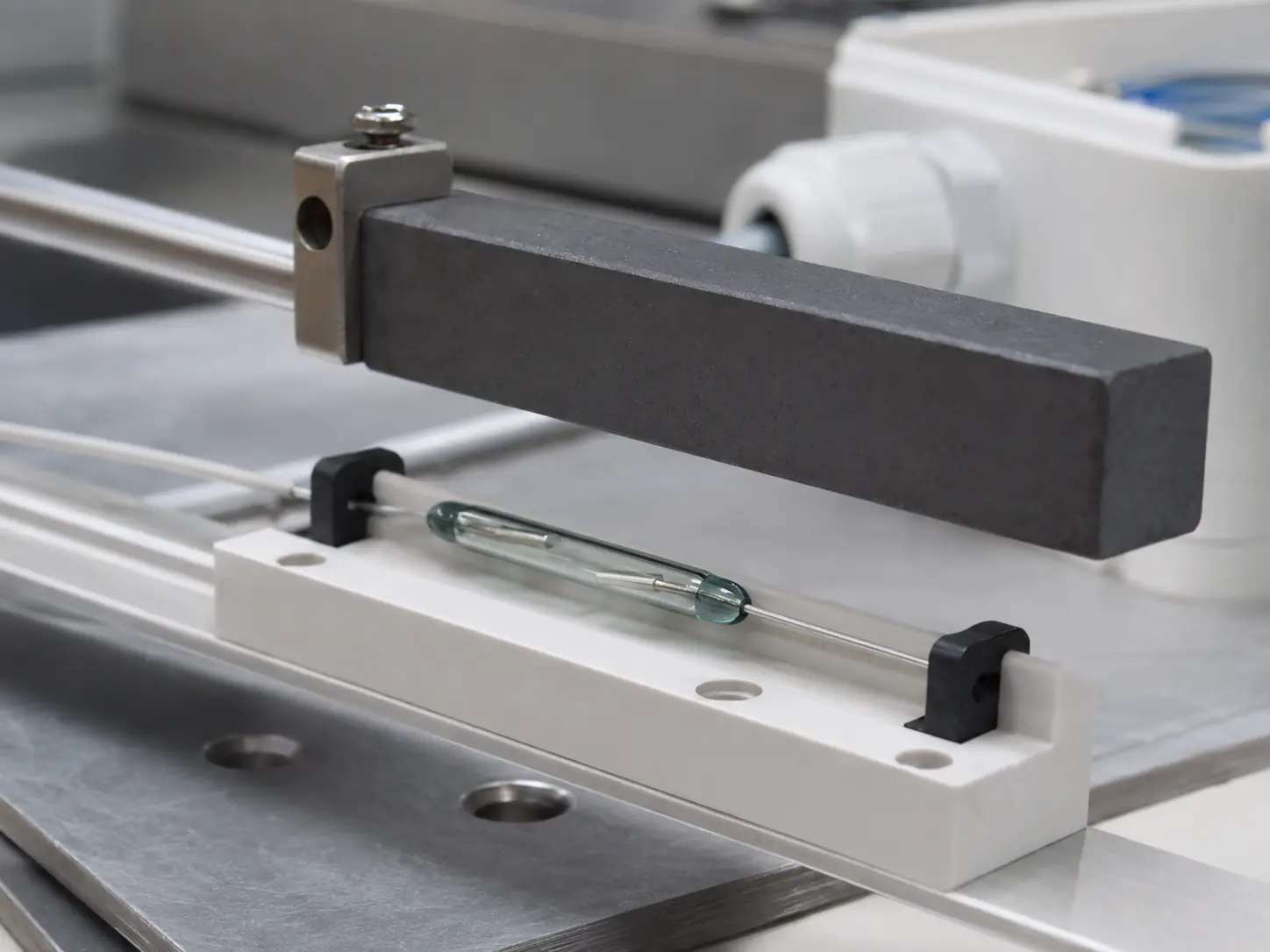
Ferrite bar magnet moving parallel to a glass reed switch

Reed Switch & Sensor Triggering

Define polarity, magnetization direction, travel path and distance to the sensing element. Validate the switch-on and switch-off positions under the specified temperature, vibration and installation conditions.

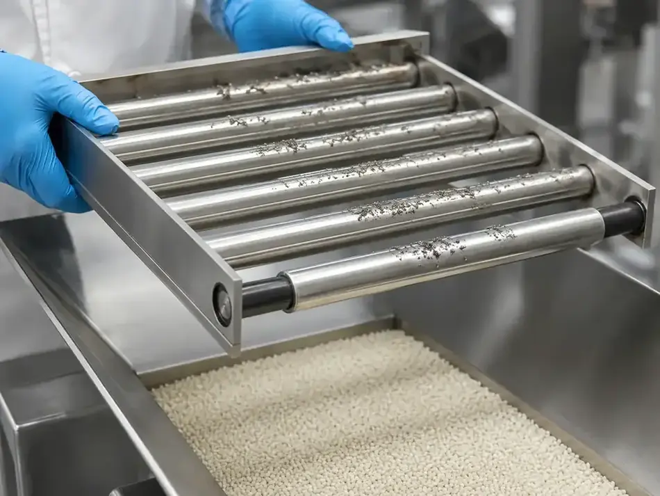
Parallel magnetic bars in stainless-steel sleeves forming an industrial magnetic grate

Magnetic Separation Equipment

Select the bar length, pole-face area and spacing to cover the material flow path. Confirm field or pull force at the working distance, together with retention and edge requirements.

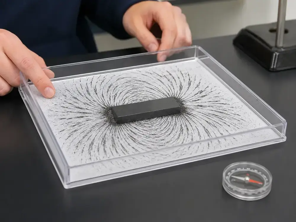
Ferrite bar magnet demonstrating magnetic field lines with iron filings

Teaching & Physics Demonstrations

Select a bar size and polarity that clearly demonstrate attraction, repulsion and magnetic field patterns. Confirm N/S marking, edge condition and magnetic response for repeatable experiments.

Documented industry presence

Ferrite Bar Project and Exhibition Evidence

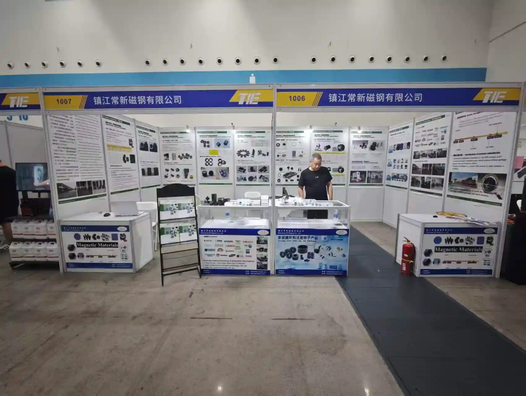
The exhibition record documents GX Magnet's participation in magnetic-material and motor-component industry events. 

GX Magnet Exhibition Booth in Taizhou 2026

GX Magnet Exhibition Booth in Taizhou 2026. Event or visit photograph documenting the people and setting shown.

GX Magnet at the 2026 Shenzhen Magnetic Materials Exhibition

Documented evidence

Quality-System and Ferrite Material Evidence

GX uses documented quality-system controls and ferrite sample compliance reports as supporting evidence. The product drawing and agreed inspection specification remain the release basis for each bar magnet project.

IATF 16949:2016

Zhenjiang GX Magnet Co., Ltd. holds valid IATF 16949:2016 certification for the manufacturing of permanent ferrite magnet components.This certification covers all production‑oriented processes for ferrite magnet manufacturing.

SGS Ferrite RoHS Compliance

Independent SGS laboratory testing delivers positive results for ferrite magnet samples under EU RoHS screening scope.

SGS Ferrite REACH SVHC

Independent SGS laboratory testing delivers positive screening results for ferrite magnet samples against REACH SVHC candidate‑list substances.

ENGINEERING AND SOURCING FAQ

Common Questions Buyers Ask About Ferrite Bar Magnets

Find practical answers on material selection, dimensional requirements, magnetization, operating conditions, inspection and the information needed for an accurate quotation.

How do Ferrite bar magnets differ from long bars and shorter ferrite blocks?

The main differences are the material route, achievable geometry, magnetic output and assembly method. Compare them in the actual magnetic circuit and operating condition; the product name alone is not enough to select the part.

How should engineers select the material for Ferrite bar magnets?

Start with ferrite grade and orientation relative to the working face. Then check the required magnetic output, geometry, temperature and commercial volume before fixing a grade in the drawing.

Which dimensions should be toleranced on Ferrite bar magnets?

Control the dimensions that set fit, air gap or working position. For this product, review length, cross-section, flatness, edge condition and magnetization direction; avoid applying a tight general tolerance to non-functional surfaces without a measurement reason.

What magnetization information is needed for Ferrite bar magnets?

Specify the magnetization axis or pole pattern, pole count where applicable, and the acceptance method. A field value must also state the measurement location, fixture or air gap so supplier and buyer evaluate the same condition.

How does temperature affect Ferrite bar magnets?

Temperature capability depends on material grade, geometry, magnetizing state and the magnetic circuit. Provide temperature, impact risk, retention method and exposure medium; GX can then review demagnetization risk and whether the proposed material route fits the duty.

How should magnetic performance be verified for Ferrite bar magnets?

Use an agreed method tied to the application: material-property testing, surface field at a defined position, flux, pull force, pole pattern or waveform. The released drawing and acceptance plan should state the instrument, fixture and limits.

What information should an RFQ for Ferrite bar magnets include?

Send the drawing or 3D model, material or magnetic target, length, cross-section, flatness, edge condition and magnetization direction, temperature, impact risk, retention method and exposure medium, expected quantity and acceptance method. State whether tooling, inserts, assembly or magnetization is included in the requested supply scope.

How are samples approved before recurring Ferrite bar magnets orders?

Agree the drawing revision, tooling state, critical dimensions and magnetic test method before sample release. Approval should identify the sample record and any deviations; recurring orders then follow the released specification, quotation and control plan.

Project inquiry

Send Your Ferrite Bar Magnet Drawing

Attach the part and assembly drawings. GX reviews bar geometry, material or magnetic target, magnetization, application conditions and inspection method before defining the sample route.

  • 2D / 3D drawing
  • Length, width, thickness, datums and critical faces
  • Material grade or magnetic target
  • Polarity, application and annual demand


No file selected

By submitting this form, you agree to provide accurate project information for evaluation. Information is kept confidential.