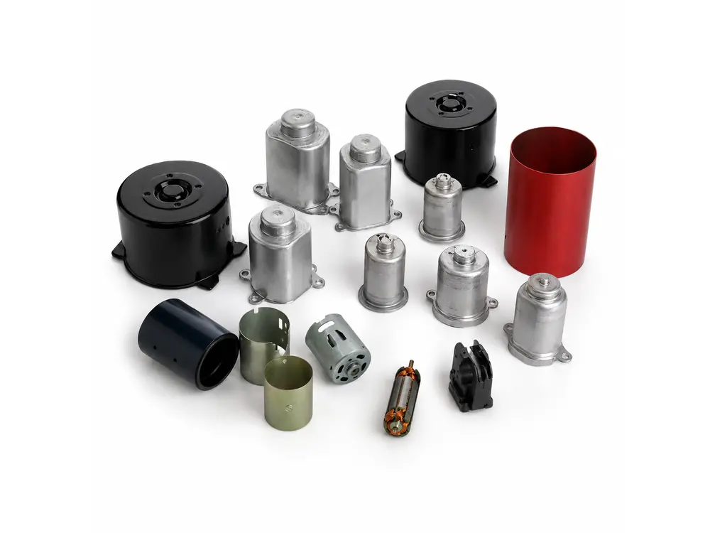
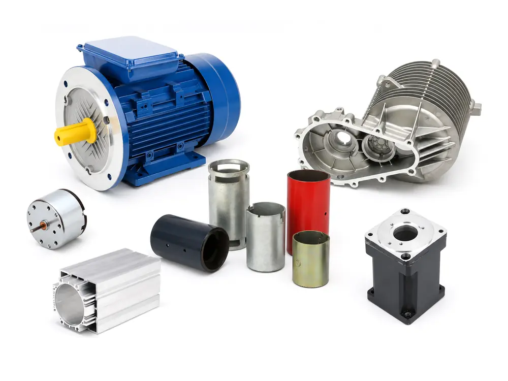
Deep-Drawn Steel Motor Can
SPCC/SPCE reference with 0.5–2.0 mm wall and typical L/D ≤2.5; final diameter, trim, pierce and flange tolerances by drawing.
Drawing-based motor component supply
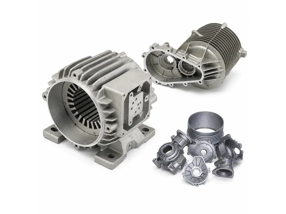
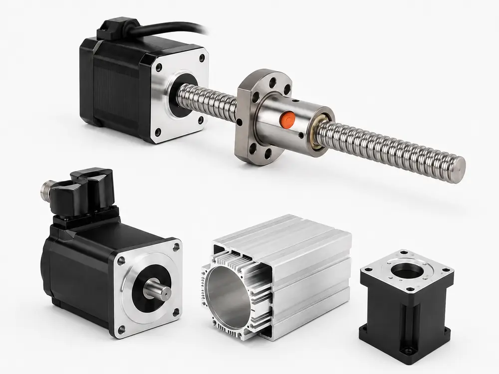
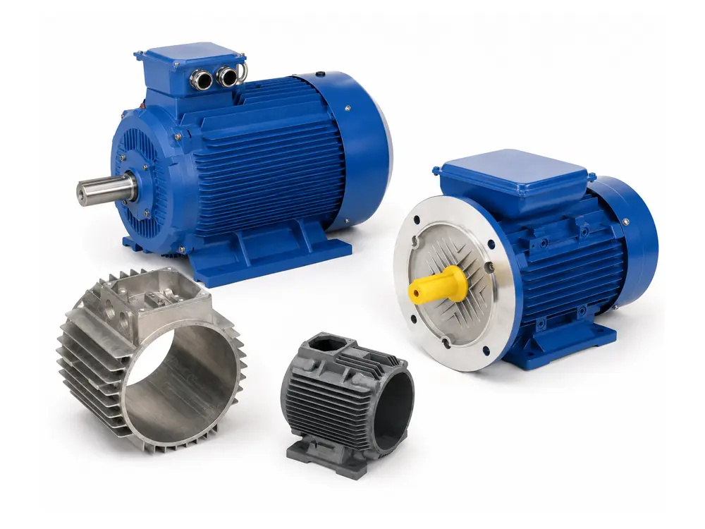
GX supplies drawing-based DC motor housings for brushed permanent-magnet motors and BLDC assemblies. Steel cans are reviewed for deep drawing or roll forming, while aluminum housings are reviewed for extrusion or casting. Magnet location, stator fit, bearing bore, end-cover interface, roundness, coating and machining datums are confirmed from the released drawing.
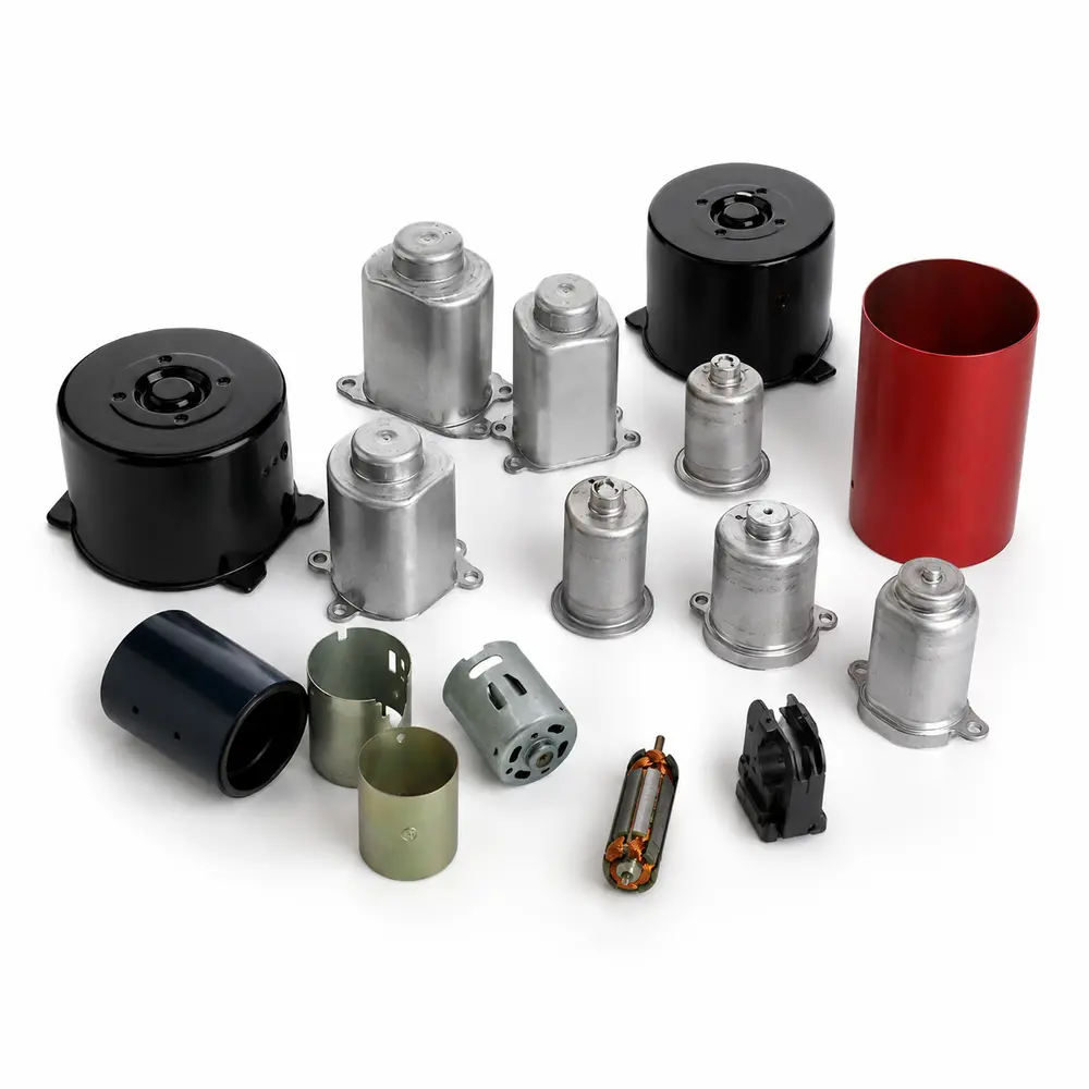










Product routes
The housing material and process depend first on whether the shell forms part of the magnetic return path or mainly provides structure and heat rejection.
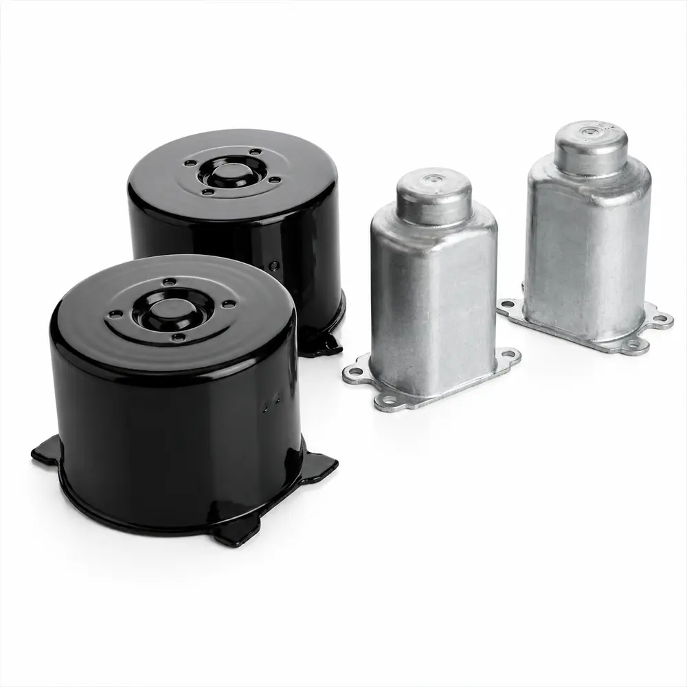
Before quotation
A complete RFQ package lets GX review the housing material, forming route, mating interfaces and inspection method before tooling or sample quotation. The drawing should connect shell geometry with stator fit, bearing location, end-cover assembly and operating conditions.
TECHNICAL PARAMETERS FOR QUOTATION
Reference ranges help buyers compare forming, machining and inspection routes. Final values are released when the housing material, drawing revision, mating interfaces, surface treatment and acceptance plan are confirmed in the quotation.
| Parameter group | Project-specific review basis | Release basis |
|---|---|---|
| Material / Route | SPCC/SPCE or SUS304 steel for deep-drawn or rolled motor cans; 6063, ADC12, A356 or drawing-specified aluminum for extruded or cast housings. | Material grade, forming route and secondary machining are confirmed in the released drawing, specification and quotation. |
| Geometry and Tolerances | Shell diameter, wall thickness, housing length, bearing bore, stator seat, end-cover fit, mounting holes, terminal openings and datums. | Critical dimensions and GD&T are released with the approved drawing and first-article dimensional report. |
| Fit and Surface Requirements | Project-defined H6–H9 fits, Ra 0.8–3.2 μm review band for critical machined surfaces, and size-based geometric control where required. | Fit class, roughness, roundness, coaxiality, runout and flatness limits are confirmed by function and inspection method. |
| Magnetic / Functional Role | Steel cans are reviewed when the shell also works as a magnetic return path; aluminum housings are reviewed mainly for structure, heat path and interface control. | Magnetic role, stator position, magnet location or heat-transfer requirement is released only when included in the drawing or BOM. |
| Operating Environment | Temperature, vibration, corrosion medium, coating, cleanliness, ingress boundary, cooling path and pressure condition when applicable. | Exposure tests, coating requirements, leakage or pressure tests are confirmed by the approved specification and acceptance plan. |
| Inspection and Acceptance | Dimensional report, CMM or gauge checks, roundness, roughness, coating inspection, leakage test and marked drawing where specified. | Inspection method, sample size, frequency, records and lot-release criteria are fixed before recurring supply. |
| Supply Boundary | Base scope covers the DC motor housing or shell and the quoted forming, coating, machining and inspection operations | Magnet fitting, bearing assembly, brush components or complete motor assembly are listed as separate BOM scope when included |
Why choose us for your project
DC motor housing sourcing should begin with the shell material, motor structure and mating interfaces. GX reviews steel cans and aluminum housings by drawing-defined diameter, wall thickness, bearing bore, stator seat, end-cover fit, roundness, coating and machining datums before the quotation route is released.
Select deep-drawn or rolled steel cans for brushed permanent-magnet motors, or extruded and cast aluminum housings for BLDC structural and thermal requirements.
Review stator seat, bearing bore, end-cover fit, mounting holes, terminal openings and magnet location together with the approved motor package.
Confirm whether the quotation covers a bare shell, coated shell, machined housing, fitted magnets or a drawing-defined mechanical subassembly.
Process linked to the requirement
The DC motor housing route is selected from the drawing, material, wall thickness and mating parts. GX reviews deep-drawn or rolled steel cans with 0.5–2.0 mm wall reference, and aluminum housings with machined stator, bearing and end-cover datums. Fit class, roughness, roundness and leakage checks are released only when defined in the drawing and inspection plan.
Steel shells are reviewed for deep drawing, roll forming, trimming, piercing and coating; aluminum housings are reviewed for extrusion, casting and secondary machining.
Bearing bore, stator seat, end-cover pilot, mounting face and coaxiality are checked against the approved datums, with project-defined H6–H9 fits where specified.
Deburring, cleaning, masking, coating and machined-surface protection are defined around the surfaces used for fit, sealing, magnet location and final assembly.

Evidence before repeat orders
DC motor housing approval is built around measurable fit and surface evidence. GX can release bearing bore, stator seat, end-cover pilot and mounting datums with project-defined H6–H9 fits, Ra 0.8–3.2 μm machined-surface review, and 0.02–0.15 mm size-based geometric-control bands. When sealing or cooling is specified, leakage or pressure testing can be set at 1.5–2× the maximum working pressure.

Bearing bore, stator seat, end-cover pilot, mounting face, coaxiality, runout and roundness are checked by CMM, gauges or dedicated fixtures before recurring supply.
Roughness, burrs, coating coverage, masking areas and cleaned interfaces are reviewed around bearing, sealing, magnet-location and end-cover assembly surfaces.
Final release can include first-article dimensions, coating checks, leakage or pressure results, sampling frequency, lot traceability and Cpk ≥1.33 reference targets for specified critical characteristics.
Product and supply scope
A DC motor housing provides the structural reference for the stator, bearings, end covers and mounting interfaces while maintaining alignment between rotating and stationary components. In brushed permanent-magnet DC motors, a steel housing can also form part of the magnetic return path and locate ferrite arc or ring magnets. Aluminum housings are commonly selected where lower weight and heat dissipation are priorities. GX supplies drawing-defined DC motor housings as bare machined shells, coated housings, magnet-fitted housings or specified mechanical subassemblies, with critical fits, interfaces and surface requirements controlled to the approved drawing and BOM.
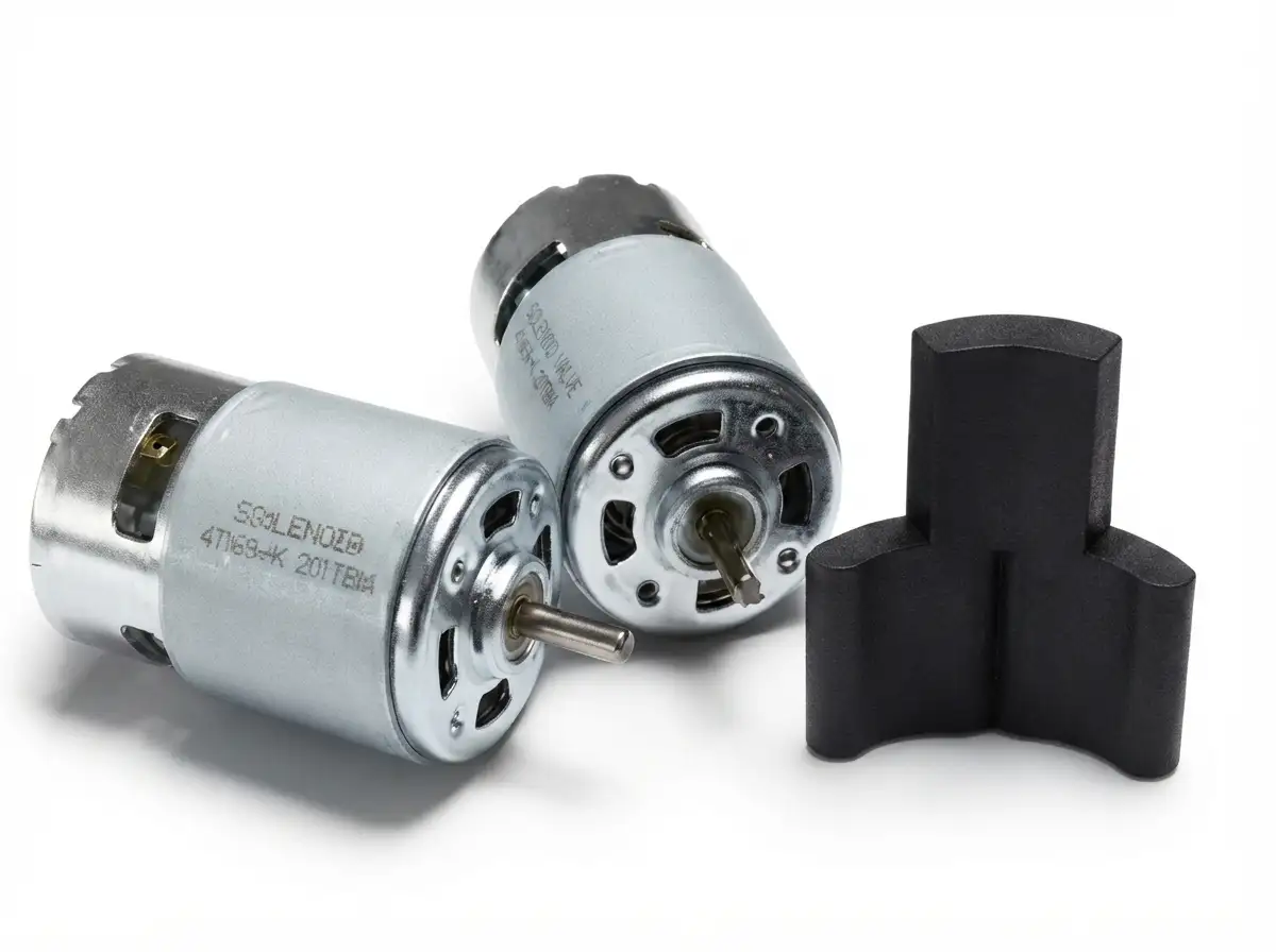
Project route
DC motor housing production is routed around the released drawing and supply boundary. GX manufacturing evidence covers deep-drawn steel housings and seamless-tube routes, followed by trimming or machining, cleaning, surface finishing and, where included in the BOM, magnet bonding or bearing-sleeve assembly.

Confirm material, wall thickness, housing geometry, datums, machining stock and supplied assembly boundary before the production route is released.
Form steel motor cans by deep drawing, or prepare seamless steel tube blanks by cutting when the drawing and housing structure require a tubular route.
Trim formed shells and machine drawing-defined bores, pilots, mounting faces, slots or other interfaces required for the motor assembly.
Remove burrs and process residues, then clean the housing before bonding, surface treatment or downstream assembly.
Apply the drawing-specified surface finish, with coating areas and protected interfaces defined before downstream assembly.
Where included in the approved BOM, housings can continue into magnet bonding, bearing or bearing-sleeve pressing and other drawing-defined mechanical assembly.
Verification
Inspection focuses on drawing-defined diameters, roundness, datums, machined interfaces, formed features and surface condition that directly affect bearing, stator, magnet and end-cover assembly.

| Control item | Method / evidence | Buyer benefit |
|---|---|---|
| Material / Structure | Material certificate, thickness check, hardness where specified, and confirmation of drawing-defined magnetic or structural requirements. | Confirms the housing material and wall condition match the approved design. |
| Diameter / Roundness | Air gauge, ring gauge, roundness tester or CMM according to the tolerance and feature being controlled. | Controls bearing, stator and end-cover fit while reducing assembly variation. |
| Datums / Machined Interfaces | CMM, height gauge or dedicated fixture checks for pilots, bearing seats, stator seats, mounting faces and hole locations. | Maintains alignment between the housing and mating motor components. |
| Formed Features / Burr | Visual, optical or fixture inspection of tabs, vents, flanges, slots, holes, edge condition and burr direction. | Prevents interference, winding damage and assembly handling problems. |
| Surface / Functional Fit | Coating-thickness, masking and roughness checks, plus gauge or trial-fit verification where required. | Protects controlled interfaces and confirms the finished housing remains assembly-ready. |
Application fit
Housing design is defined by mounting, load, thermal path, environment and validation requirements—not by housing shape alone.
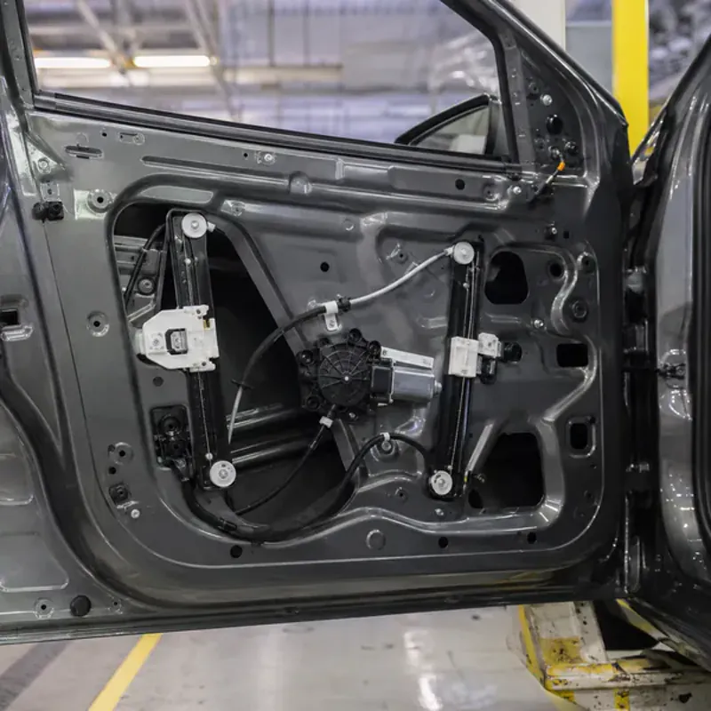
Housing design is driven by bearing and stator fits, end-cover datums and corrosion exposure. Typical programs combine drawing-defined H6–H9 fits with validation across -40 to 125°C operating conditions.
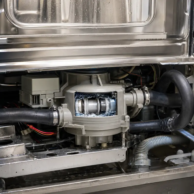
Roundness, bearing alignment and sealing interfaces are critical under vibration and moisture exposure. Where pressure sealing is required, test pressure can be specified at 1.5–2× maximum working pressure.
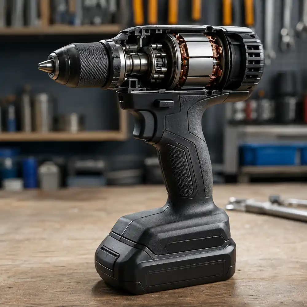
Compact housings balance low mass, bearing alignment and heat transfer. Critical machined interfaces may use H6–H9 fits with Ra 0.8–3.2 μm surface requirements where defined by the drawing.

Housing accuracy directly affects stator centering, rotor air gap and end-cover alignment. Drawing-defined coaxiality and runout can be controlled within 0.02–0.15 mm bands depending on housing size and interface.
Project control
GX controls drawing revision, material and process requirements, sample approval and critical-characteristic records against the agreed project scope. Certification claims apply only to the documented company, process and product scope.
Housing material, interfaces, surface finish, supplied components and acceptance criteria follow the current released drawing and BOM.
Critical dimensions, assembly fit, surface condition and project-specific tests are recorded to establish the approved production baseline.
Incoming, in-process and final controls follow the agreed inspection method, fixture, sampling plan and acceptance limits. Where process capability is specified, Cpk ≥1.33 can be used as the reference target for defined critical characteristics.
Project evidence is defined during quotation and may include material records, dimensional or CMM reports, surface roughness, coating, leakage, cleanliness and marked-drawing inspection results.

Buyer communication
GX Magnet meets OEM buyers and engineers at industrial exhibitions to review DC motor housing drawings, mating interfaces and supply scope. Face-to-face discussion helps clarify datums, assembly fits, process risks and missing RFQ details before tooling or quotation is finalized.
Compare housing materials, formed geometry, machined interfaces and surface-finish requirements against the drawing.
Confirm bearing, stator, end-cover, mounting, cooling and sealing interfaces before the production route is fixed.
Align DFM, sample approval, required evidence, change control and recurring-order expectations before project release.
Engineering and sourcing FAQ
Eight practical questions covering housing selection, drawing definition, critical fits, surface requirements, inspection and production release.
The difference is determined by motor architecture, load path, bearing arrangement, cooling and manufacturing route. Compare the drawing interfaces and validation requirements rather than choosing by frame appearance alone.
Review stamped, drawn, cast or machined material route. The selected route must support the required datum structure, machining access, thermal behavior, surface treatment and projected volume.
The critical dimensions are those controlling rotor-stator alignment and final assembly. Typical review points include bearing bore, end-cover fit, brush or terminal interfaces, mounting pattern and concentricity, but the customer drawing must identify the functional datum scheme and inspection priority.
Control them from a consistent machining datum and verify the relationship, not only each size independently. The acceptance plan should define bore size, position or concentricity, face runout and the gauge or CMM method.
Testing is required when the housing forms a sealed cavity, coolant path or specified environmental barrier. Define coating, sealing, leakage criteria, corrosion exposure and motor duty, test pressure or method, allowable leakage and the surfaces included in the test boundary.
Inspection should combine material or casting checks with critical machined dimensions, datum relationships, thread and surface-condition checks. Coating thickness, cleanliness, leakage or packaging controls are added only when the released specification requires them.
Provide 2D drawings and 3D data, material and process preference, bearing bore, end-cover fit, brush or terminal interfaces, mounting pattern and concentricity, coating, sealing, leakage criteria, corrosion exposure and motor duty, annual quantity and acceptance method. Identify supplied inserts, machining scope, surface treatment and any required test fixtures.
Agree the drawing revision, datum strategy, critical-characteristic list and inspection method before production approval. The first-article package should record results and approved deviations; recurring supply follows the released drawing, quotation and control plan.
Request for quotation
Send 2D/3D files, mating interfaces, material and process requirements, operating limits, surface finish, sample quantity, annual demand and validation expectations.