
Magnet System
Ferrite Y25–Y40 · NdFeB N35–N55 · bonded Br 0.20–0.78 T — selected by flux, temperature, corrosion and geometry.
Motor Rotor · Permanent Magnet Rotor
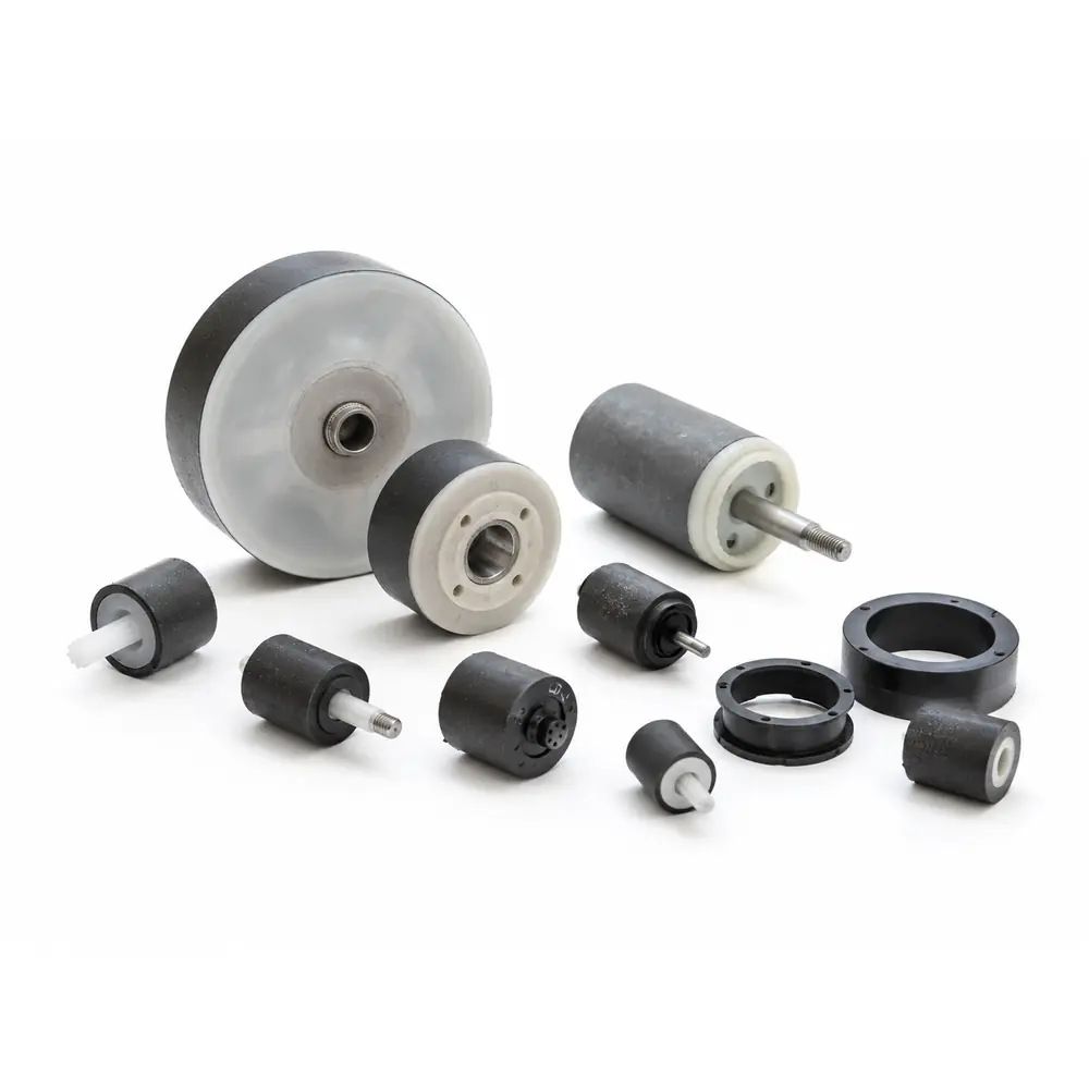
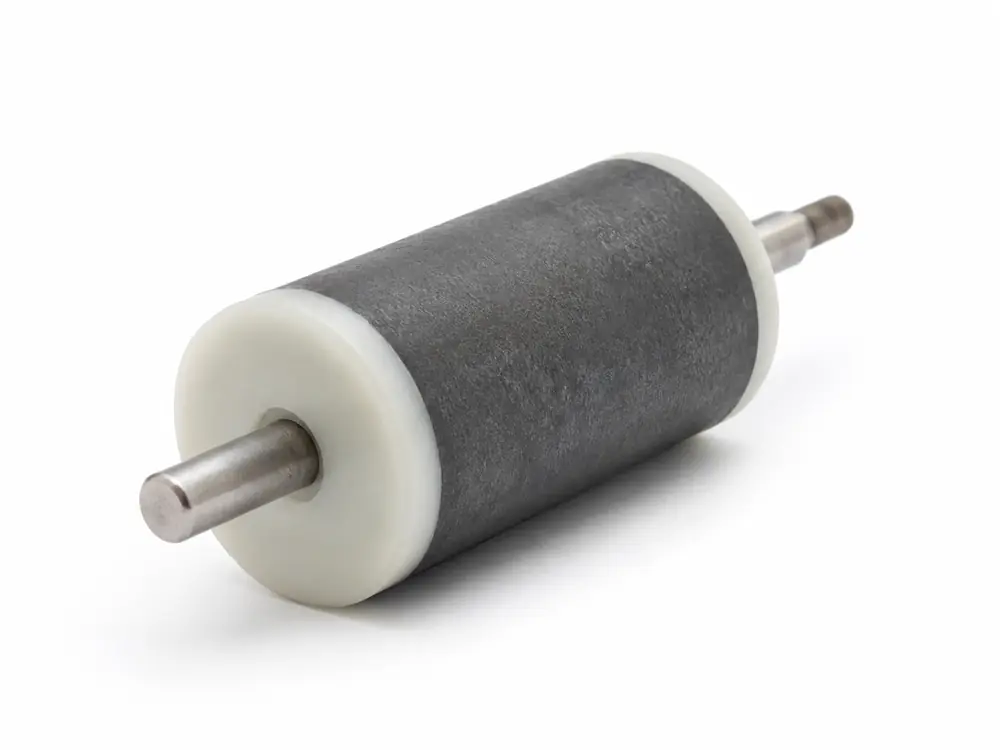
GX Magnet supplies drawing-defined permanent magnet rotors and rotor subassemblies using sintered ferrite, sintered NdFeB or bonded magnet systems. Material grade, pole pattern, shaft or hub interface, magnet retention, air-gap geometry, runout and balance are reviewed as one rotor specification.







Drawing variables
Magnetic function, mechanical interfaces, speed and the mating stator must be reviewed as one rotor system.
Engineering data
The specification is confirmed from the approved rotor drawing, magnetic target, mating stator, operating speed, environment and validation plan.
| Parameter | Specification / Review Basis |
|---|---|
| Structure / Supply Scope | 2–64 poles · inner / outer rotor — magnet component or shaft + core/carrier/hub + magnet mechanical assembly. |
| Component Materials | Ferrite Y25–Y40 · NdFeB N35–N55 with N/M/H/SH/UH/EH/AH grade families · bonded Br 0.20–0.78 T · electrical/solid steel core · steel/stainless shaft · PA66/PPS inserts — adhesive follows the application. |
| Dimensions / Fits | OD Ø8–150 mm · ID Ø2–80 mm · length 5–100 mm · shaft Ø2–30 mm · IT6–IT9 — final dimensions and bearing fits follow the approved drawing. |
| Poles / Magnetic Output | 2–64 poles · radial / axial / multipole · surface flux 50–500 mT · pole position ±1°–±3° — fixture, distance and temperature must be agreed. |
| Geometric Accuracy | Concentricity 0.01–0.10 mm · TIR 0.02–0.15 mm · straightness 0.01–0.10 mm/100 mm · Ra 0.4–3.2 μm — controlled from drawing datums. |
| Mechanical / Rotational | Retention 50–3,000 N · torque 0.1–100 N·m · balance G0.4–G6.3 · rated ≤20,000 rpm · maximum ≤30,000 rpm — test limits depend on rotor structure. |
| Environment / Acceptance | −40 to 150°C · overspeed 1.2× · salt spray 24–240 h · N48H reference demag ≤4% at 100°C × 2 h · AQL 0.65–1.5 — final method is project-defined. |
Typical review ranges only. Material grade, rotor size, speed, balance, retention and environmental limits are confirmed by the approved drawing, sample and agreed test conditions.
Project screening
A workable quotation needs the rotor drawing, magnetic target, mechanical interfaces and operating limits—not only a rotor name or sample photo.
Use the display positions to identify the supply route closest to the drawing. Final scope is confirmed from interfaces, materials, operating conditions and inspection responsibility.
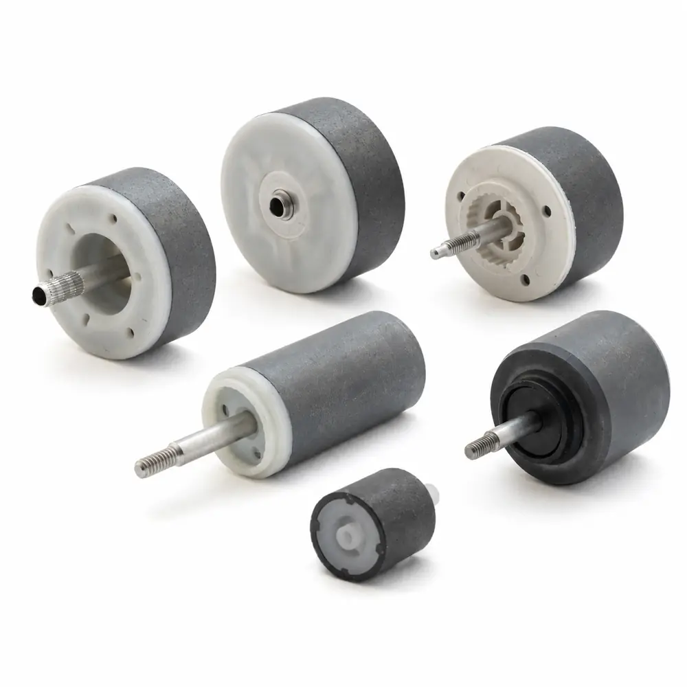
Ferrite or NdFeB rotor assemblies for BLDC/PMSM pumps, appliances and automotive actuators, supplied to drawing with defined pole layout, core/hub interface and operating speed.

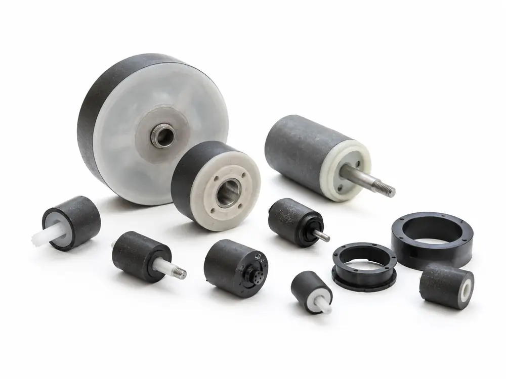
Sintered ferrite magnets assembled with a shaft, hub or carrier for pumps, appliances and auxiliary motors. Pole layout, air-gap surface, mechanical interfaces, runout and balance are specified by drawing.

Compact rotor assemblies for applications requiring higher magnetic output within limited installation space. Magnet grade, coating, retention method and thermal-demagnetization risk are evaluated from the actual operating conditions.
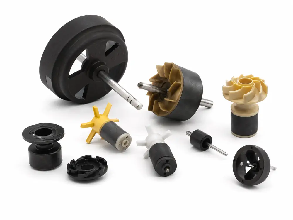
Bonded ferrite or bonded NdFeB rotors for sensors, compact motors, automotive switches and appliance drives, with multipole waveform, inserts and molded interfaces controlled by project.

Arc or block magnets are positioned on a core, hub or carrier when the design requires a larger diameter, a specific pole arc or a material unavailable as a one-piece ring. Magnet position and retention are controlled at assembly level.
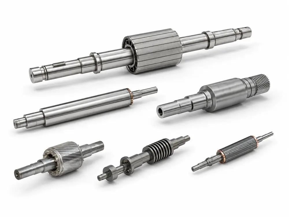
Advanced slicMagnets, shaft, hub or core are supplied as one inspected rotor assembly. Bearing datums, torque-transfer features, runout, balance, magnet retention and magnetic output are controlled according to the released drawing.ing, grinding, and coating capabilities to meet the strictest tolerances and surface finish demands.
Send us your rotor drawing, motor configuration and operating conditions. GX Magnet can review the magnet material, pole pattern, shaft or hub interface, retention method, runout, balance and inspection requirements before quotation.
Product and supply scope
A permanent magnet rotor carries a fixed magnetic field on the rotating member of a motor. Magnet material and grade, pole layout, core or carrier, shaft or hub, retention method and air-gap surface jointly determine whether the assembly matches the motor.
GX supplies the drawing-approved rotor or mechanical rotor subassembly. The quotation covers only the confirmed BOM, assembly operations and acceptance plan; a stator, bearing system, electronics or complete motor is not included unless separately stated.
Project route
Ferrite, sintered NdFeB and bonded magnet routes use different upstream processes, then converge at drawing-controlled assembly, magnetization, balance and inspection.
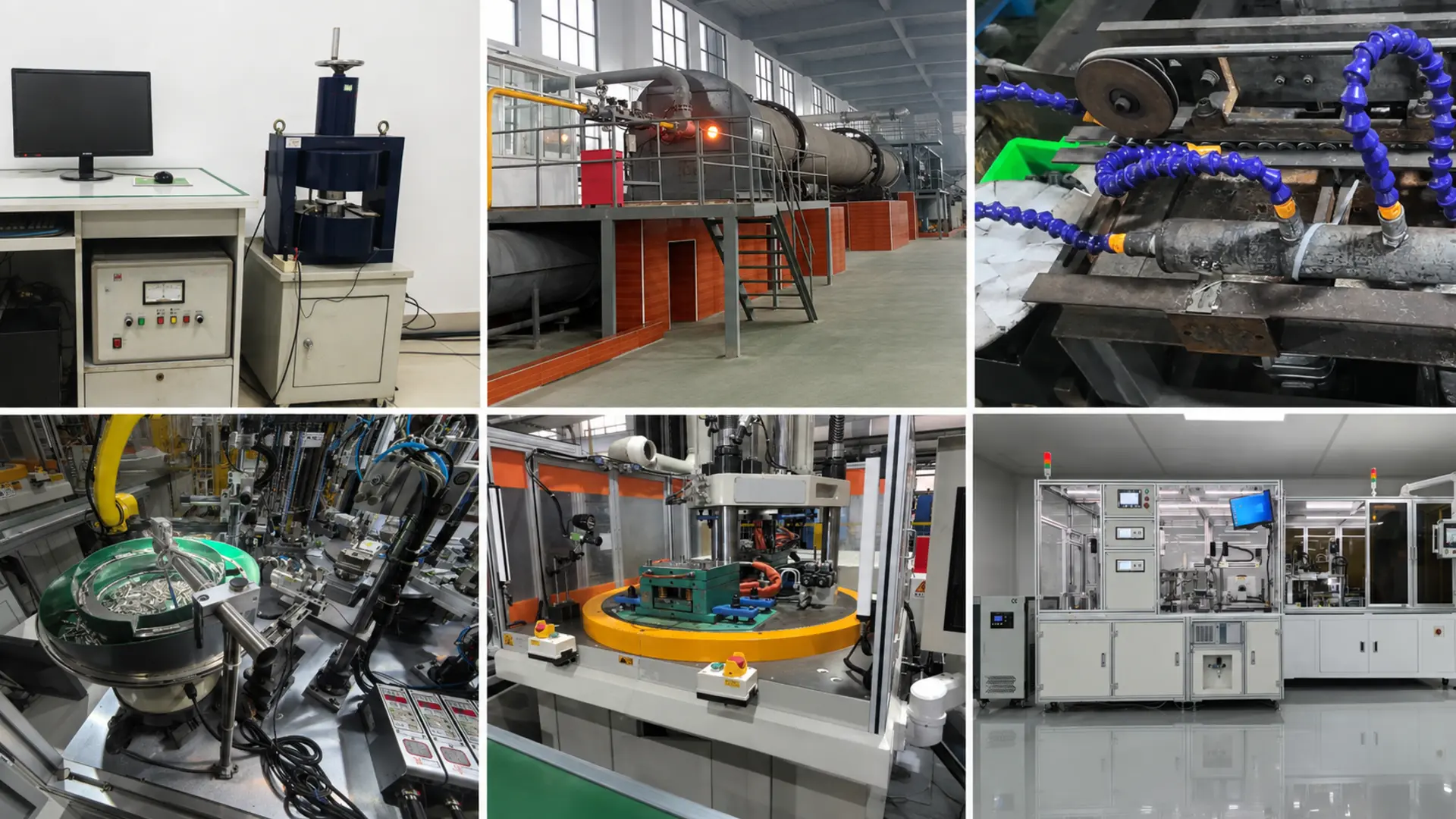
Drawing, BOM, pole map, magnetic target, speed, temperature, medium, validation and demand are reviewed together.
Ferrite powder pressing and sintering, NdFeB sintering and coating, or bonded mixing and molding is selected by project.
Magnets are ground, cut, coated or molded as required; shafts, cores, hubs and carriers are inspected before loading.
Positioning, press fitting, bonding, mechanical locking, welding, overmolding or encapsulation follows the approved process.
Pole pattern, surface-flux waveform, assembly TIR, static or dynamic balance and agreed functional checks are verified.
Approved sample, drawing revision, control plan, inspection frequency and traceable batch records govern recurring supply.
Verification
The control plan links drawing datums and material controls to the pole pattern, magnetic response, retention, runout, balance and environmental requirements agreed for the rotor.

| Inspection item | Control approach | Why the buyer needs it |
|---|---|---|
| Dimensions and datums | Projector, CMM, gauges and roughness equipment used as applicable to magnet, shaft, core and assembly features | Controls fits, concentric interfaces and the working air gap |
| Concentricity / TIR | Shaft datum, bearing seats, rotor OD and air-gap surface checked to the drawing | Supports stable rotation and consistent electromagnetic clearance |
| Magnetic performance | Material properties, total flux, surface-flux scan or waveform checked under the agreed fixture and distance | Makes magnetic results repeatable and comparable |
| Poles and retention | Magnetization direction, pole sequence and position verified; push-pull or speed testing added when specified | Confirms commutation, assembly security and application fit |
| Balance / environment | Static or dynamic balance plus thermal demagnetization, thermal shock, humidity, salt spray or PCT by project | Connects production release to speed and service conditions |
Application fit
Each application requires its own combination of material, pole waveform, air-gap geometry, shaft or hub interface, speed, medium and validation evidence.
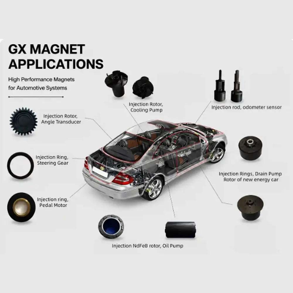
Compact pump and actuator rotors reviewed for temperature, pole waveform, retention, balance and traceability.
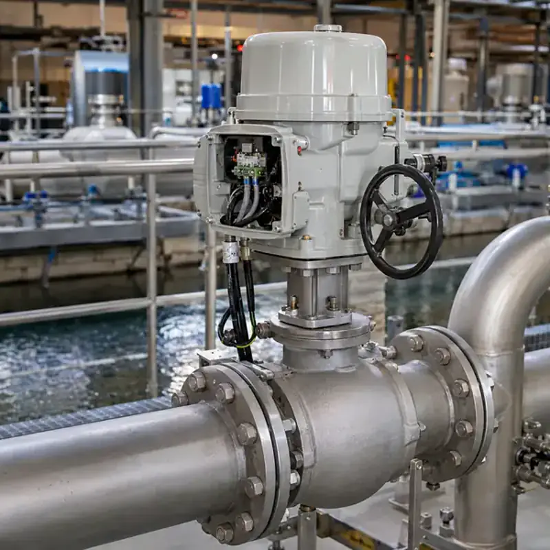
Dry or wet-runner projects reviewed for fluid exposure, overmold or encapsulation boundary, runout and magnetic output.
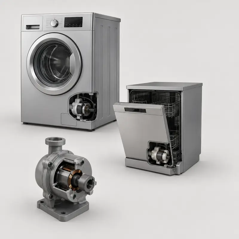
Dishwasher, drain, circulation and fan-motor rotors controlled for multipole pattern, noise-related geometry and batch consistency.

Higher-speed structures reviewed for shaft fits, torque transfer, magnet retention, TIR and dynamic balance requirements.
Quality-system support
GX Magnet applies its IATF 16949:2016 quality system to drawing revision, material and process control, sample approval, inspection planning and recurring production records.
Material grade, magnet geometry, mechanical datums, pole map, retention and appearance follow the released revision.
Dimensions, magnetic results, fit, TIR, balance and agreed reliability tests are recorded before production release.
Incoming, in-process and final controls use the agreed method, fixture, sampling level and acceptance limits.
Available project evidence can include dimensional reports, magnetic-property or surface-flux data, coating thickness, balance results and specified environmental-test records. Exact documents are agreed at quotation.
Buyer communication
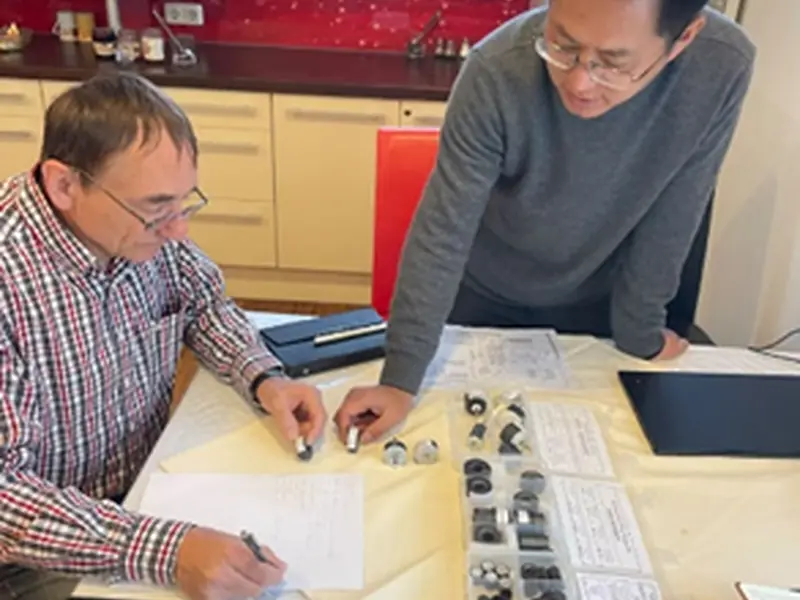
GX Magnet uses industrial exhibitions to present magnetic materials, rotor assemblies and motor-component capabilities to OEM buyers, engineers and sourcing teams.
Bring the rotor drawing, mating-stator information or a magnetic-function question. The discussion can identify supply boundaries, interface risks and RFQ information needed before formal engineering review.
Compare magnet layouts, shaft or hub interfaces and rotor forms before choosing the quotation route.
Review air gap, speed, runout, balance, environment and validation expectations.
Plan drawing review, sample approval, inspection evidence and recurring communication.
GX Magnet
GX Magnet’s established strengths include hard-ferrite material and ring-magnet production, supported by permanent-magnet material, molding, rotor assembly, magnetization and inspection routes for drawing-defined projects.
In-house ferrite powder, pressing, sintering, grinding and multipole magnet production support material-to-component control.
Automatic or project-specific loading, positioning, press fitting, bonding, welding, overmolding and balancing are reviewed by BOM.
Material testing, magnetization, surface-flux scanning, waveform analysis and project-defined functional checks support release.
FAQ
Clarify the drawing, material route, interfaces, test conditions and supply boundary before comparing quotations or releasing samples.
Provide 2D and preferably 3D rotor files, the BOM and mating-stator or interface drawing, motor type, pole map, magnetic target and test condition, rated and maximum speed, temperature, medium, duty cycle, sample quantity and annual demand.
Ferrite offers corrosion resistance and cost stability; sintered NdFeB supports higher magnetic output in limited volume; bonded materials suit complex geometry and multipole consistency. Final selection also depends on temperature, coating, retention, speed and the defined magnetic target.
Yes, when the parts and assembly operations are listed in the approved drawing and BOM. GX reviews bearing seats, fits, datums, torque transfer, retention, TIR, balance and inspection responsibility before confirming scope.
Define magnetization direction, pole count, pole sequence, angular zero, working face and the measurement fixture, distance and temperature. GX can verify material properties, total flux, surface-flux distribution or waveform according to the agreed method.
The drawing should identify the rotational datum, bearing seats, air-gap surface, TIR limit, balance planes and residual-unbalance or grade requirement. ISO 21940-11 can be referenced for rigid-rotor balance when agreed.
Yes, as project-specific conditions. State the fluid, pressure, temperature, chemical exposure, rated and overspeed values, duty cycle and retention or leakage boundary. Overmolding, encapsulation, coating and speed tests are then confirmed rather than assumed.
The released drawing and BOM, material grade and lot controls, approved process route and sample, measurement fixtures, control plan, sampling frequency and acceptance limits form the production baseline.
Material-grade data and prior project cases are feasibility references only. Finished-rotor flux, waveform, demagnetization, balance, retention and environmental results depend on geometry and test conditions and become commitments only when written into the approved specification.
Request for quotation
Send the motor type, 2D/3D files, BOM, magnet and pole requirements, shaft or hub interfaces, operating limits, validation plan, sample quantity and annual demand.