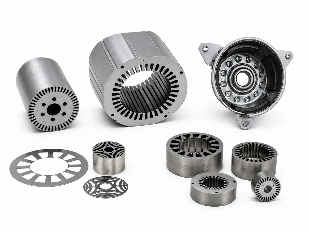
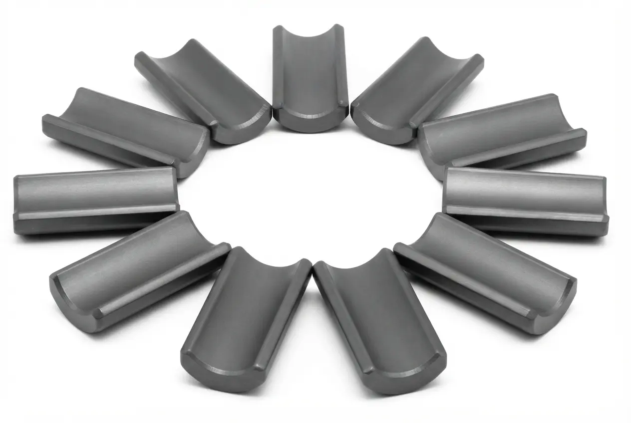
Interlocked Stack
Interlock points, stack height and datums are defined to the approved lamination drawing.
Motor Stator · Stator Core Assembly
We manufacture electrical-steel stator cores and lamination stacks to customer drawings. Supply boundary: stator core / lamination stack only. Copper windings, coil winding, impregnation, and lead wires are excluded.
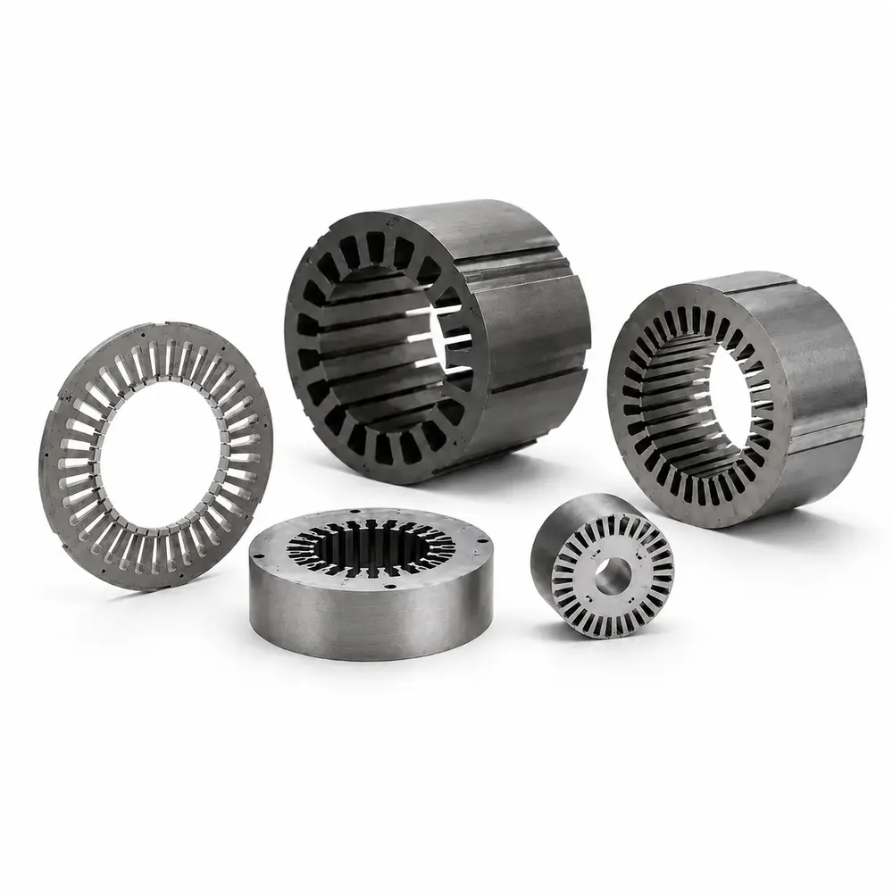
Core configurations
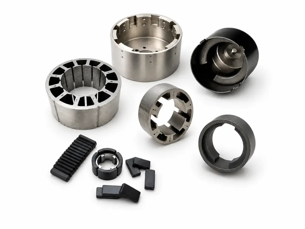
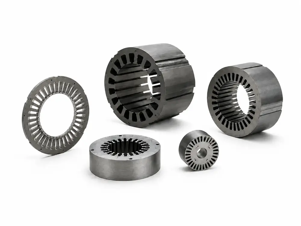
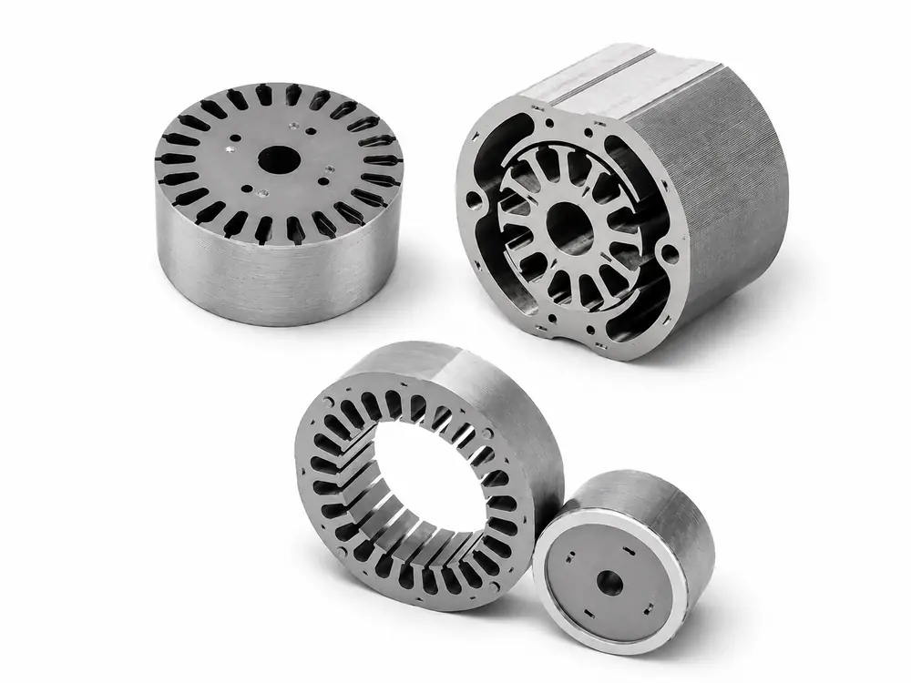
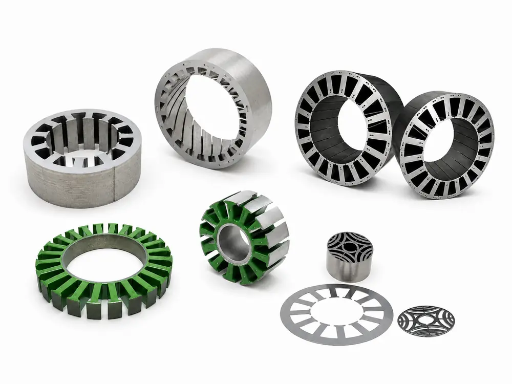
Each structure is reviewed from the electrical-steel lamination drawing, stack method, critical datums and inspection requirements.
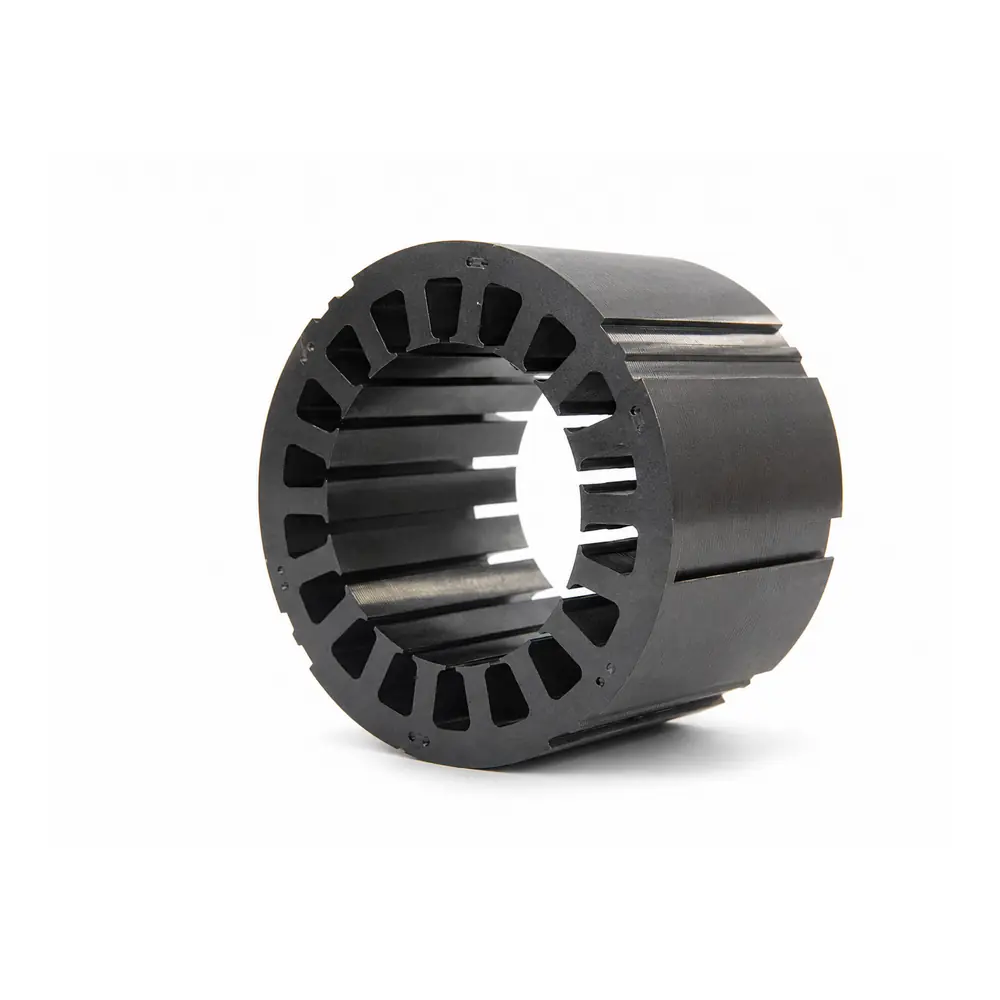
| Parameter | Specification / Range |
|---|---|
| Product Type | Motor stator core assembly / electrical-steel lamination stack |
| Material Grade | 35A300–50W470 reference family; final grade follows the approved loss and frequency requirement |
| Lamination Thickness | 0.20–0.65 mm reference range |
| Outer Diameter | 30–1150 mm reference range; geometry and tooling dependent |
| Stack Height | 5–600 mm reference range |
| Magnetic Flux Density | ≥1.6 T conditional project target under the agreed test condition |
| Core Loss | ≤2.0 W/kg at 50 Hz for selected low-loss grades under the agreed test condition |
| Burr / Flatness | Burr ≤0.02 mm and flatness ≤0.03 mm as conditional drawing targets |
| Stacking Method | Interlocked, bonded, welded, riveted or clamped according to drawing and geometry |
| Operating Temperature | –40°C to +180°C, subject to electrical-steel coating and project validation |
| Supply Boundary | Stator core / lamination stack only; copper winding, coil insertion, terminals, bus bars, VPI and winding tests are excluded |
Core capability
Each point combines a measurable range with its relevance to stator-core sourcing. Final values are confirmed against the approved drawing and test condition.
Product and supply scope
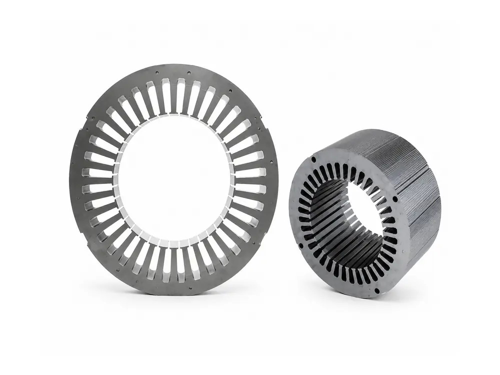
A Motor Stator Assembly is the stationary electromagnetic core of an electric motor, built from precision-stamped electrical-steel laminations that are stacked, joined, and finished to customer-approved drawings. GX manufactures the stator iron core and lamination stack only — controlling material grade, lamination geometry, stack height, joining method, and inspection datums. Copper wire, coil winding, winding insertion, terminals, bus bars, sensors, VPI (Vacuum Pressure Impregnation), and winding electrical tests are outside the supply scope and sourced by the customer separately.
Core manufacturing route
The route focuses on electrical-steel selection, lamination geometry, stacking, joining and dimensional inspection.
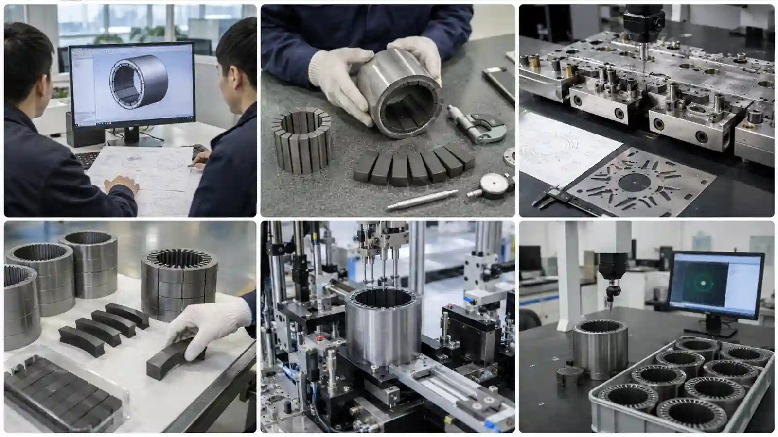
OD, bore, slots, tooth width, yoke, stack height, datums and annual volume requirement are reviewed.
Electrical-steel grade, thickness, coating and loss target are confirmed.
Laser-cut samples or stamping tooling are selected based on order volume and part geometry.
Slot profile, bore, OD, burr and lamination flatness are controlled to drawing requirements.
Interlocking, bonding, welding, riveting or clamping is applied as specified.
Dimensions, stack height, flatness, concentricity, runout and burr are inspected and recorded.
Core inspection
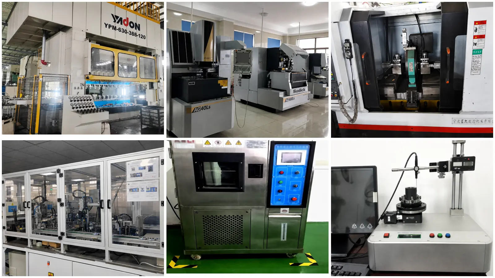
The control plan follows the approved drawing and agreed dimensional or magnetic test condition.
| Inspection Item | Control Approach | Buyer Relevance |
|---|---|---|
| OD / bore / slots | Critical geometry and datums checked by agreed gauges or measurement method | Controls housing fit, rotor clearance and slot consistency |
| Stack height | Measured after the specified stacking and joining route | Controls active length and motor assembly position |
| Burr / flatness | Conditional targets ≤0.02 mm / ≤0.03 mm where stated on the drawing | Supports lamination contact, fit and downstream assembly |
| Concentricity / runout | Bore and outer datums evaluated to the approved inspection plan | Supports stable rotor air gap |
| Material / loss | Grade records and agreed magnetic test conditions linked to the project | Connects supplied steel to the approved electromagnetic design |
Application fit
Application suitability depends on material grade, lamination thickness, slot geometry, stack dimensions, joining method and operating duty.
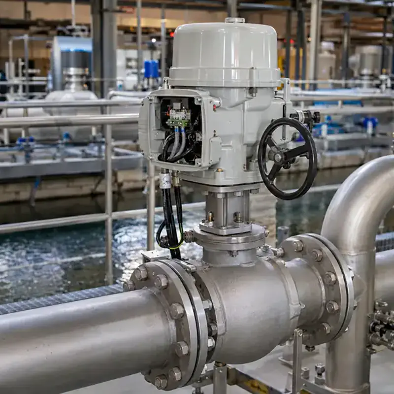
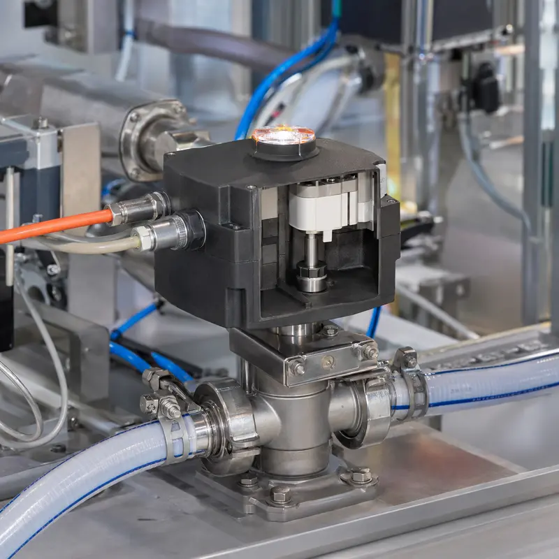
Core dimensions, slots and stack construction are controlled for the approved motor frame and rotor interface.
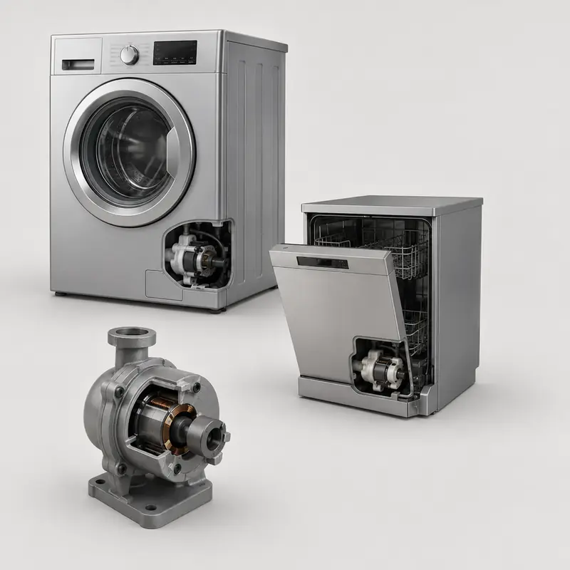
Bore, housing fit and lamination condition are reviewed for repeatable assembly.
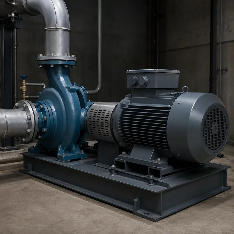
Loss target, noise-related geometry and production consistency follow the released drawing.
Segmented or large-diameter stator cores are evaluated from drawings, volume and inspection access.
Quality-system support
GX Magnet applies its IATF 16949 quality system to drawing revision, material confirmation, sample approval and project-defined core inspection.
Project-specific inspection records and magnetic data can be provided according to the approved drawing and agreed test conditions.
Buyer communication
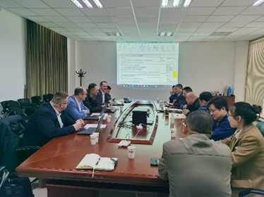
GX uses industrial exhibitions to discuss electrical-steel materials, stator-core structures and drawing-based manufacturing with OEM engineers and sourcing teams.
Bring OD, bore, slot profile, stack height, material grade, annual demand and inspection requirements to define the quotation route.
GX Magnet
GX Magnet supports drawing-based stator iron-core and magnetic-component projects for automotive, appliance, pump, HVAC and industrial applications.















FAQ
These answers define the stator iron-core supply scope and initial engineering review.
GX supplies the electrical-steel stator iron core or lamination stack defined by the approved drawing.
No. Copper wire, coils, winding, terminals, bus bars, VPI and winding electrical tests are not included.
No. They are initial screening ranges. Final capability depends on material, geometry, tooling, stack method and inspection requirements.
Provide 2D/3D drawings, material grade, lamination thickness, OD, bore, slot geometry, stack height, critical tolerances, sample quantity and annual demand.
Request for quotation
Include the stator-core drawing, material, dimensions, stack method, inspection requirements, sample quantity and annual demand.