








GX MAGNET Logo

Ferrite Magnet

Ferrite Arc Magnet Manufacturer

GX Magnet produces sintered ferrite arc magnets to customer drawings for OEM motor magnetic circuits. Geometry, magnetic targets, magnetization and the installed air gap are reviewed before sample approval.

  • Arc ferrite magnet geometry produced from customer drawings
  • Loose magnet segments supplied for the customer’s motor assembly
  • Approved samples and specifications define production release
Supply statement: drawing-based ferrite arc magnet production
GX Magnet ferrite arc magnets for OEM motor assemblies

Supporting Global Motor, Pump, Appliance and Automotive Programs

GX manufactures drawing-defined ferrite magnets and motor components for appliance, automotive, pump and industrial motor applications.

Bosch logo
Midea logo
Siemens logo
WEG logo
Gree logo
Shimge logo
Copreci logo
Buhler logo
Samsung logo
Nidec logo

Before quotation

Confirm Ferrite Arc Magnet Inputs Before Quotation

A consistent parameter package from procurement and engineering enables GX to evaluate manufacturability, confirm quotation scope, plan tooling and inspection methods, and establish clear sample-approval criteria before production.

Drawing, geometry and interfaceProvide the 2D/3D drawing and revision: inner/outer radii, arc angle or chord, thickness, length, datums, bonding face and installed air gap.
Material and functional targetConfirm sintered strontium ferrite grade and anisotropic orientation selected for the motor circuit; state material target, pole orientation and gap flux or another agreed motor-circuit measure.
Operating boundaryState temperature, moisture, vibration, adhesive exposure and opposing field.
Demand and acceptanceConfirm sample and annual demand, drawing revision, arc-profile inspection and magnetic acceptance method.

Finished Product Display

Choose an Existing Ferrite Form or Specify a Custom Part

Compare sintered ceramic ferrite shapes, ferrite ring geometries and injection-molded ferrite options to select the appropriate product route. For a drawing-defined part, submit the material or magnetic target, critical dimensions, magnetization requirements and operating conditions for engineering review.

Why choose us for your project 

Independent Magnetic Material R&D

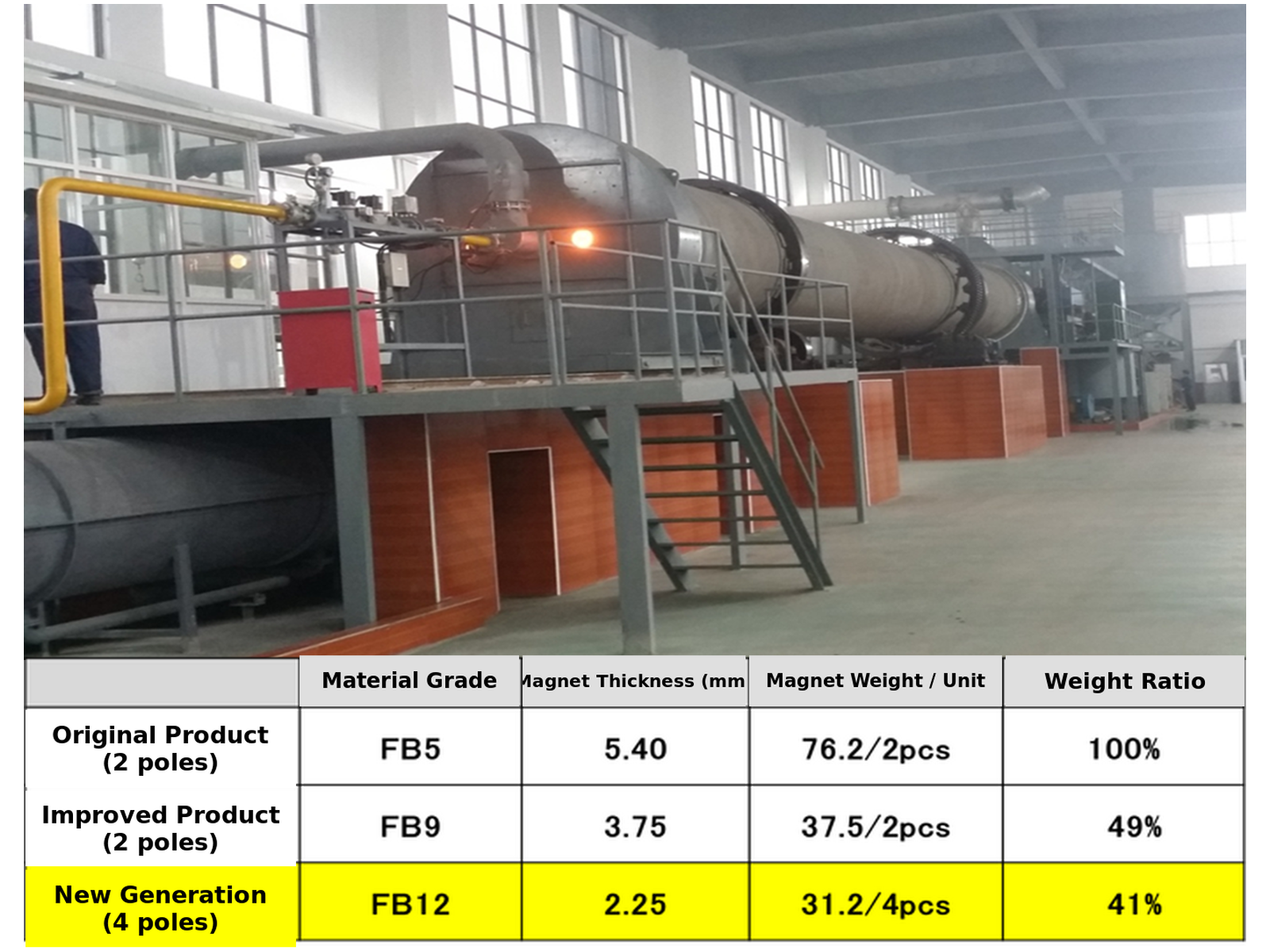
Our in‑house rotary‑kiln calcination line supports independent formula development. We produce high‑grade ferrite powder 100% for internal use. It enables miniaturized arc magnets down to 2.25 mm wall thickness, batch magnetic fluctuation controlled within ±3%.

Ferrite arc magnet geometry for motor air-gap and assembly review

Geometry Chain

Calcination parameters are tuned together with magnet geometry. Optimized powder grain structure supports FB12 high‑grade material. Magnet assembly weight can be reduced to 41%versus traditional 2‑pole solution, without sacrificing magnetic flux.
Magnetic Direction

Tightly‑controlled calcination improves intrinsic Hcj up to 4200 Oe. Stable powder quality guarantees consistent magnetic orientation, critical for thin‑wall mini‑size motor magnetic circuits.

Assembly Interface

Stable raw‑material performance lowers sintering deformation, dimensional tolerance can reach ±0.05 mm. Annual capacity for thin‑wall arc‑segment magnets hits 6.5 million pcs.

Why choose us for your project 

Arc Ferrite Segments for Automotive & Small‑Appliance Motors

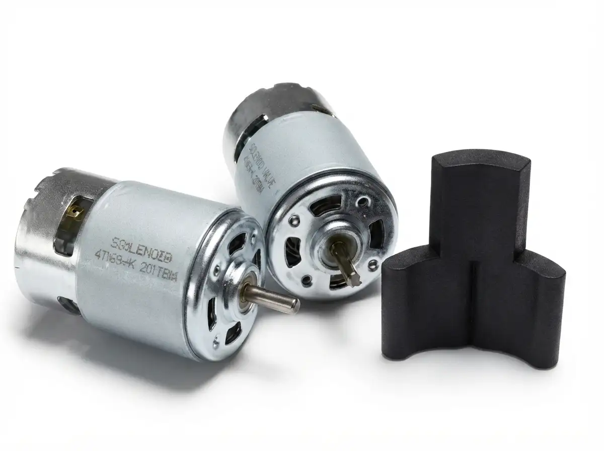
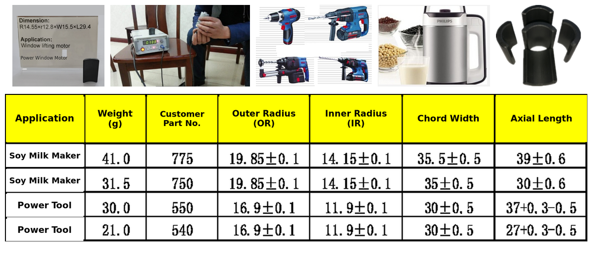
We supply mature arc ferrite segments for automotive window lifting motors, power tools and home appliance motors. With upgraded FB12-grade material, miniaturized design and stable mass production capability, the magnet assembly can achieve smaller volume, lower weight and consistent magnetic performance.

GX ferrite powder preparation sintering and finishing process
01

Miniaturized & Lightweight Design

Upgraded FB12-grade ferrite reduces the wall thickness to 2.25 mm for automotive window lifting motor magnets. The total magnet assembly weight can be reduced to 41% compared with the traditional 2-pole solution.

02

Mature SKUs for Power Tools & Home Appliances

Existing mass-production sizes cover single-piece weight from 21.0 g to 41.0 g. Suitable for soybean-milk machines, power tools and similar small motor applications.

03

Stable Mass Production & Customization

Strict dimensional tolerance and stable magnetic performance support batch supply. Custom arc-segment dimensions, grades and magnetic requirements are available based on customer drawings.

Why choose us for your project 

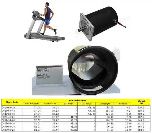
Heavy‑Duty Arc Ferrite Segments for Treadmill Drive Motors

Material grade alone cannot guarantee performance for large‑size heavy ferrite magnets. Our sample‑release workflow validates geometry, weight, magnetic property and anti‑deformation performance before mass production for treadmill projects.

Ferrite arc magnets reviewed for an automotive auxiliary motor application

Drawing

Confirm inner‑outer radii, thickness, axial length, weight tolerance, bonding surfaces and edge acceptance for heavy‑weight large arc segments.

Magnetic Setup

Define magnetization direction, test fixture and air‑gap requirement for high‑power treadmill motors, covering single‑piece weight up to 845 g.

Sample Approval

Inspect sintering deformation, dimension deviation, magnetic flux and chipping risk; verify performance under high‑load working conditions.

Recurring Supply

Deploy released drawing specifications. Stable batch quality for both home‑use and commercial treadmill motor orders, existing SKU weight range 320‑845 g.

Product and supply scope

What Is a Ferrite Arc Magnet?

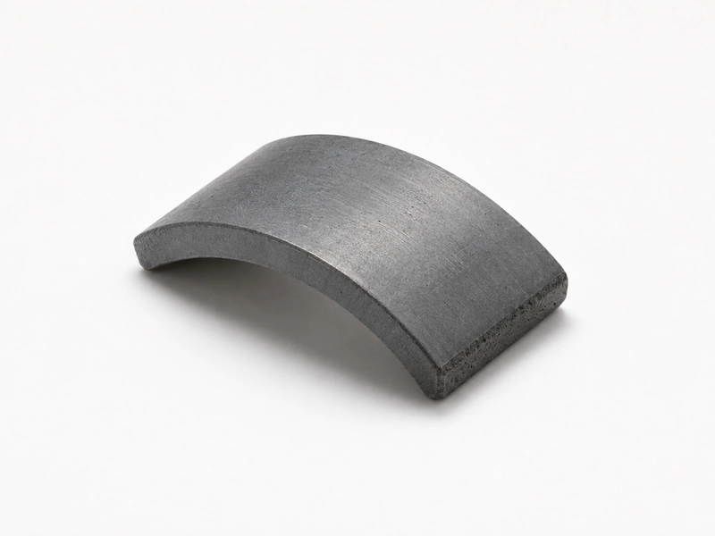
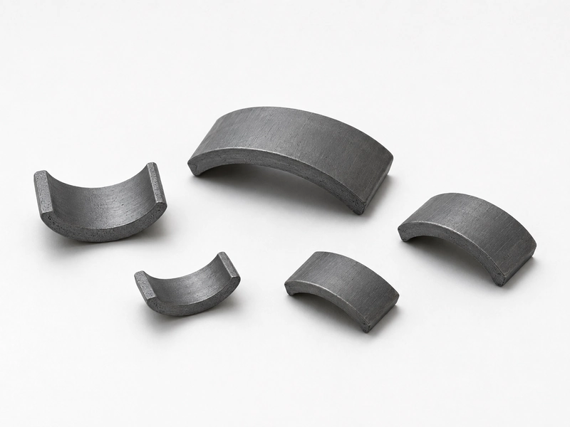
A ferrite arc magnet is a curved sintered permanent-magnet segment used to form part of a circular magnetic circuit. Arc ferrite magnets are commonly specified around a rotor or inside a motor housing, where segment geometry and the working air gap affect the installed magnetic result.

GX supplies individual ferrite arc magnets according to the approved drawing and magnetic requirement. The customer’s carrier, housing, rotor, adhesive system and final assembly remain separate unless their supply scope is confirmed for that project.

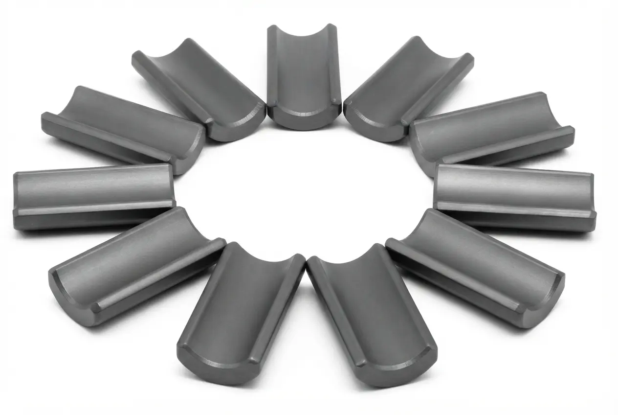
Ferrite arc magnet segments with curved inner and outer surfaces
Drawing-based supplySegment geometry, material or magnetic target and magnetization are defined before sampling.
Production releaseApproved drawing, sample and inspection criteria control recurring orders.
Project evaluationAir gap, bonding surface, operating temperature and mechanical environment are reviewed with the application.
Separate scopeSteel carriers, housings, shafts and final motor assembly are not included in an arc magnet quotation unless confirmed separately.

FERRITE ARC SELECTION GUIDE

Select Ferrite Arc Geometry and Magnetization for Your Assembly

Use the motor or housing interface to define the radius, thickness, arc coverage and axial length. Then specify the material orientation, magnetization direction, polarity sequence and bonding features required by the drawing.

Ferrite arc magnets in drawing-defined segment geometries

Match the Curved Interface

Provide the stator or housing ID, rotor OD, magnet position and working air gap. These inputs determine the inner radius, outer radius and radial thickness of the ferrite arc.

Define Arc Coverage and Length

Specify the arc angle or chord length, axial length, number of segments per assembly and required end spacing. Include the drawing datums used for dimensional inspection.

Select Orientation, Magnetization and Polarity

Specify isotropic or anisotropic ferrite, the required orientation axis, and radial, parallel or another drawing-defined magnetization direction. Identify the N/S face and installed polarity sequence for each segment.

Define Bonding and Edge Features

Identify the bonding face, adhesive thickness, chamfers, locating features and edge or chipping criteria. These details control seating position, bond-line consistency and the installed air gap.

FERRITE ARC MAGNET RFQ PARAMETERS

Select Ferrite Arc Magnet Parameters for Your Motor Application

The table follows the engineering review sequence for ferrite arc magnets. Reference ranges support initial evaluation; the final grade, inner and outer radius, arc angle, thickness, axial length, magnetic target, bonding interface and acceptance limits are confirmed in the released drawing, approved specification, quotation and control plan.

Parameter groupProject-specific review basisConfirmation and Release Evidence
Material / routeSintered strontium ferrite; grade selected from the required coercivity and energy targetApproved strontium ferrite grade and magnetic orientation; Br, Hcb, Hcj and (BH)max report at 20°C when specified.
Geometry and tolerancesInner/outer radius, arc angle or chord, thickness, axial length, datums and chamfersReleased drawing defines inner and outer radius, arc angle or chord, thickness, axial length, datums, chamfers and tolerances; verified by the first-article profile report.
Magnetic or functional requirementMaterial properties plus installed-gap flux or another agreed motor-circuit measureApproved finished-part limits for installed-gap flux, surface field or another motor-circuit target, with the measurement position, air gap, fixture and temperature defined.
Mechanical / assembly interfacePole orientation, bonding face, mating diameter and installed air gapApproved bonding face, mating diameter, adhesive system, bond-line thickness and pole orientation; assembly fit or retention testing when specified.
Operating environmentTemperature, vibration, moisture, adhesive exposure and opposing fieldAgreed limits for temperature, vibration, moisture, adhesive exposure and opposing field; environmental tests include defined duration and pass criteria.
Inspection and acceptanceProfile/dimensional inspection plus defined field, flux or functional checkControl plan defines profile and dimensional inspection, magnetic measurement method, fixture, sample size, frequency, acceptance limits and lot-release records.
Supply boundaryArc magnet segment; bonding or rotor assembly only when separately quotedQuotation and drawing identify the supplied scope—arc segments, bonded magnet set or rotor assembly—and the included magnetization, bonding, inspection, packaging and documentation.

Process route

How Sintered Ferrite Arc Magnets Move from Drawing to Release

The geometry, material requirement and magnetic direction define the process and inspection route.

01

Requirement Review

Drawing, arc dimensions, magnetic target, polarity and assembly conditions are checked together.

02

Powder Preparation

The ferrite material route is set against the approved material or magnetic requirement.

03

Pressing and Orientation

The segment is formed with the approved geometry and magnetic-direction requirement.

04

Sintering and Finishing

Sintering is followed by finishing of drawing-defined surfaces and critical dimensions.

05

Magnetization and Sample Approval

Direction and polarity are checked with the dimensional and magnetic sample results.

06

Production Inspection

Approved dimensional, appearance and magnetic criteria are used for production release.

Verification

Inspection Points Specific to Arc-Shaped Magnet Segments

The control plan links curved geometry and polarity to the customer’s assembly fit and magnetic acceptance requirement.

Project-defined control items
Inspection item Control approach Why the buyer needs it
Arc geometry Inner radius, outer radius, thickness, height and arc or chord dimensions checked against the drawing Controls fit and circumferential spacing
Datums and bonding surfaces Drawing-defined reference faces and edge condition inspected to agreed criteria Supports positioning and adhesive-gap consistency
Magnetic properties Agreed material or magnetic parameters checked under specified conditions Connects the part to the approved magnetic design
Polarity / magnetization Direction and polarity verified against the approved orientation drawing Prevents incorrect segment installation
Appearance Cracks, chips and edge condition evaluated against the agreed acceptance standard Reduces handling and assembly disputes

Application fit

Motor Projects That Use Ferrite Arc Magnets

Application fit depends on the segment-to-carrier interface, working air gap, polarity layout and operating environment.

Ferrite arc magnets for automotive auxiliary motor projects

Automotive Auxiliary Motors

Automotive auxiliary motors require the ferrite arcs to maintain the specified air gap and bonded position under temperature cycling and vibration. Define the stator bore, arc span, thickness, pole orientation, adhesive system and operating temperature. First-article approval checks the arc profile, installed-gap flux and retention after the agreed environmental tests.

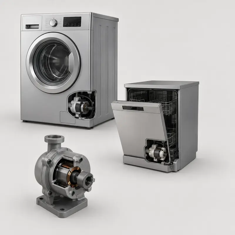
Ferrite arc magnets for appliance and pump motor projects

Appliance and Pump Motors

For appliance and pump motors exposed to moisture or hot/cold water, define the stator bore, working air gap, arc length, magnetic target and fluid-temperature cycle. Sample approval checks dimensional fit, polarity and gap flux before and after the specified exposure, together with the bonded interface.

Ferrite arc magnets for fan and HVAC motor projects

Fan and HVAC Motors

Fan and HVAC motors depend on consistent field distribution during extended operation. Specify the segment count, arc coverage, working air gap, pole sequence, operating speed and temperature. Approve matched-set dimensions, pole symmetry and flux distribution to control variation between assembled motors.

Ferrite arc magnets for industrial motor projects

Industrial Motors

Industrial-motor programs may require larger ferrite arcs and increased mechanical retention. Define the stator bore, segment dimensions, working air gap, duty condition, operating temperature and bonding method. Validate the arc profile, installed-gap magnetic output and retention under the agreed thermal and vibration conditions before recurring production.

Documented evidence

Arc Geometry and Ferrite Material Inspection Evidence

GX uses documented quality-system controls and ferrite sample compliance reports as supporting evidence. The product drawing and agreed inspection specification remain the release basis for each arc magnet project.

IATF 16949 Certified Manufacturing

GX manufactures permanent ferrite components under an IATF 16949-certified quality management system, supporting documented process control, product traceability and recurring-production requirements.

SGS-Verified RoHS Compliance

Submitted ferrite magnet samples have passed SGS screening against the applicable EU RoHS restricted-substance requirements, providing third-party material-compliance evidence for customer review.

SGS-Verified REACH Compliance

Submitted ferrite magnet samples have passed SGS REACH SVHC screening within the tested scope, providing documented third-party evidence for material-compliance review and project approval.

Customer and industry presence

Motor-Segment Projects Discussed With OEM Teams

Customer logos indicate organizations served by GX; they are not presented as product endorsements.

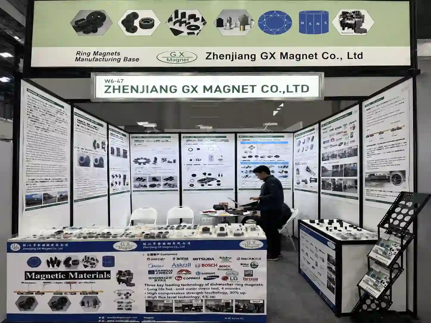
GX Magnet Booth at Manufacturing World Tokyo 2026

GX Magnet Booth at Manufacturing World Tokyo 2026. Event or visit photograph documenting the people and setting shown.

GX Magnet booth and magnetic-component samples displayed at Manufacturing World Tokyo 2026

Engineering and sourcing FAQ

Common Questions When Sourcing Ferrite Arc Magnets

Eight practical answers covering material-grade selection, arc geometry, dimensional tolerances, magnetic targets, bonding interfaces, operating conditions, sample validation and recurring-production controls.

How do Ferrite arc magnets differ from motor arc segments and generic ferrite blocks?

The main differences are the material route, achievable geometry, magnetic output and assembly method. Compare them in the actual magnetic circuit and operating condition; the product name alone is not enough to select the part.

How should engineers select the material for Ferrite arc magnets?

Start with strontium-ferrite grade and anisotropic orientation. Then check the required magnetic output, geometry, temperature and commercial volume before fixing a grade in the drawing.

Which dimensions should be toleranced on Ferrite arc magnets?

Control the dimensions that set fit, air gap or working position. For this product, review inner and outer radii, arc angle, thickness, pole orientation and working air gap; avoid applying a tight general tolerance to non-functional surfaces without a measurement reason.

What magnetization information is needed for Ferrite arc magnets?

Specify the magnetization axis or pole pattern, pole count where applicable, and the acceptance method. A field value must also state the measurement location, fixture or air gap so supplier and buyer evaluate the same condition.

How does temperature affect Ferrite arc magnets?

Temperature capability depends on material grade, geometry, magnetizing state and the magnetic circuit. Provide working temperature, opposing field, bonding method and motor duty; GX can then review demagnetization risk and whether the proposed material route fits the duty.

How should magnetic performance be verified for Ferrite arc magnets?

Use an agreed method tied to the application: material-property testing, surface field at a defined position, flux, pull force, pole pattern or waveform. The released drawing and acceptance plan should state the instrument, fixture and limits.

What information should an RFQ for Ferrite arc magnets include?

Send the drawing or 3D model, material or magnetic target, inner and outer radii, arc angle, thickness, pole orientation and working air gap, working temperature, opposing field, bonding method and motor duty, expected quantity and acceptance method. State whether tooling, inserts, assembly or magnetization is included in the requested supply scope.

How are samples approved before recurring Ferrite arc magnets orders?

Agree the drawing revision, tooling state, critical dimensions and magnetic test method before sample release. Approval should identify the sample record and any deviations; recurring orders then follow the released specification, quotation and control plan.

Project inquiry

Send Your Ferrite Arc Magnet Drawing

Attach the segment and assembly drawings. GX reviews the arc geometry, material or magnetic target, magnetization, application conditions and inspection method before defining the sample route.

  • 2D / 3D drawing
  • Inner / outer radius, height and arc definition
  • Material grade or magnetic target
  • Polarity, application and annual demand

No file selected

By submitting this form, you agree to provide accurate project information for evaluation. Information is kept confidential.