
Magnetic Compound
Br 0.20–0.78 T · Hcb 160–520 kA/m · Hcj 400–1,120 kA/m — bonded ferrite or bonded NdFeB selected according to the required magnetic output and operating temperature.
Bonded Magnet System
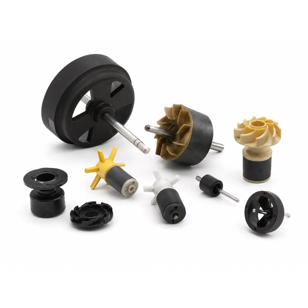
GX Magnet makes custom bonded magnet rotors from customer drawings. Injection-molded and compression-bonded options support multipole magnetization, built-in inserts and reliable mechanical fit.









Project screening
A bonded rotor review begins with the magnetic compound, molding route, pole pattern, mechanical insert and operating conditions—not just the outside dimensions.
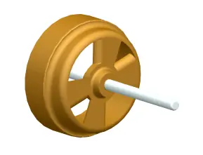
GX provides drawing-based bonded magnet rotors for motors, pumps, sensors, appliances and automotive actuators. Bonded ferrite or bonded NdFeB can be molded around a shaft, hub or insert to integrate complex geometry with a defined multipole pattern. Each rotor is developed around the required dimensions, magnetic waveform, operating temperature, speed and assembly interface.


Product and supply scope
A bonded magnet rotor is made by combining magnetic powder with a polymer binder and then molding or compacting the mixture into the required rotor geometry. The process can produce multipole patterns, thin sections, integrated inserts and complex shapes that may be difficult to achieve with separately assembled sintered magnets.
GX evaluates bonded ferrite and bonded NdFeB options for each project. Magnetic output, operating temperature, mechanical strength, moisture exposure, insert design, magnetization pattern and production volume must be considered together before the material and process are confirmed.
Rotor design variables
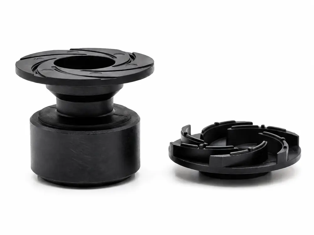
The magnetic compound, rotor geometry, inserts, magnetization pattern and operating conditions must be combined in one manufacturable specification.
Engineering data
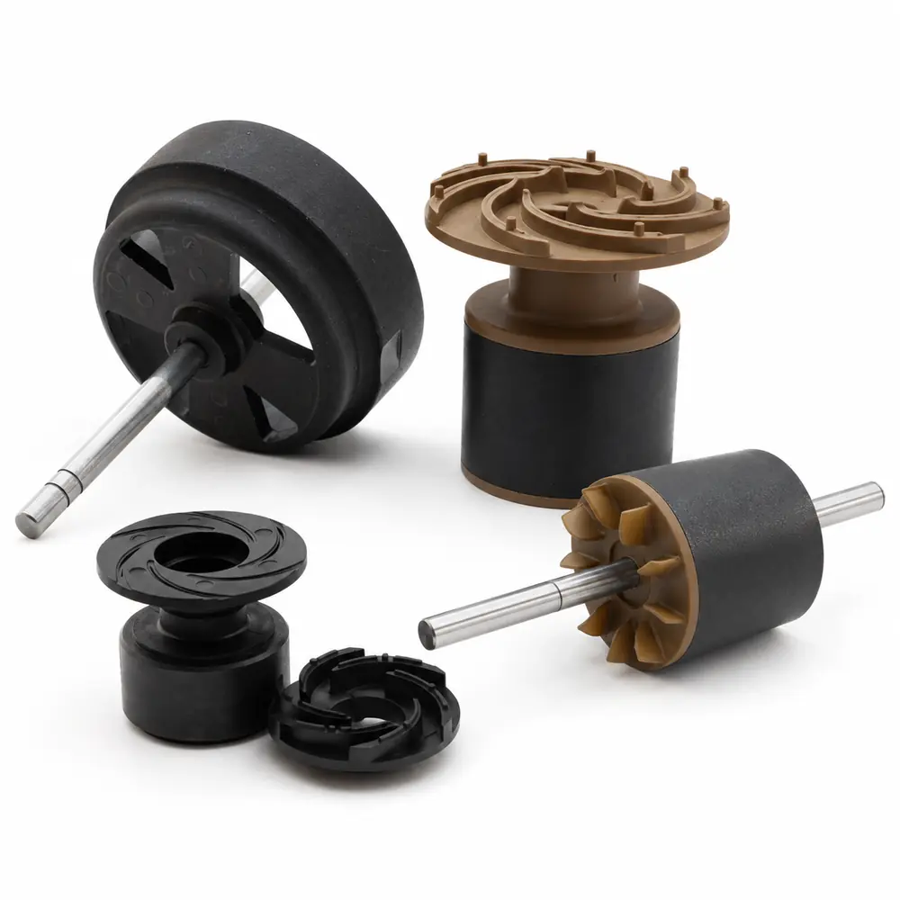
The final specification is based on the bonded material system, molding route, insert design, pole map, operating speed, service environment and validation plan.
| Parameter | Specification / Review Basis |
|---|---|
| Structure / Supply Scope | 2–64 poles · injection-molded or compression-bonded construction — magnetic ring or sleeve, or a bonded rotor integrated with a shaft, hub or insert. |
| Magnetic Compound | Br 0.20–0.78 T · Hcb 160–520 kA/m · Hcj 400–1,120 kA/m · (BH)max 12–92 kJ/m³ — combined reference ranges for bonded ferrite and bonded NdFeB; they do not represent a single compound. |
| Dimensions / Inserts | OD Ø8–120 mm · ID Ø2–80 mm · length 5–80 mm · shaft Ø2–30 mm · IT6–IT9 tolerance grades — final insert and overmold geometry follows the approved drawing. |
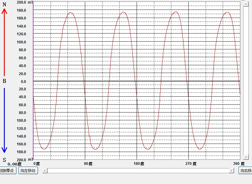
| Poles / Magnetic Output | 2–64 poles · radial, axial or multipole magnetization · pole-position tolerance ±1°–±3° — magnetic flux and waveform are measured using an agreed fixture, distance and temperature. |
| Geometric Accuracy | Concentricity 0.02–0.15 mm · TIR 0.03–0.20 mm · Ra 0.8–3.2 μm — the molding datum and air-gap surface are inspected together. |
| Mechanical / Rotational | Retention force 30–2,000 N · torque 0.05–50 N·m · balance grade G1–G6.3 · rated speed ≤15,000 rpm · maximum speed ≤20,000 rpm — limits depend on the binder, insert design and wall thickness. |
| Environment / Acceptance | Maximum operating temperature 100–150°C, depending on the compound and rotor design · salt-spray exposure 24–240 h · overspeed factor 1.2× · AQL 0.65–1.5 — final test and sampling plans are project-defined. |
These are typical review ranges only. Magnetic properties vary by compound and density; final rotor limits are confirmed in the approved material specification and drawing and under the agreed test conditions.
Application examples
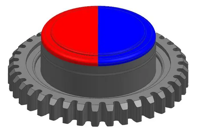
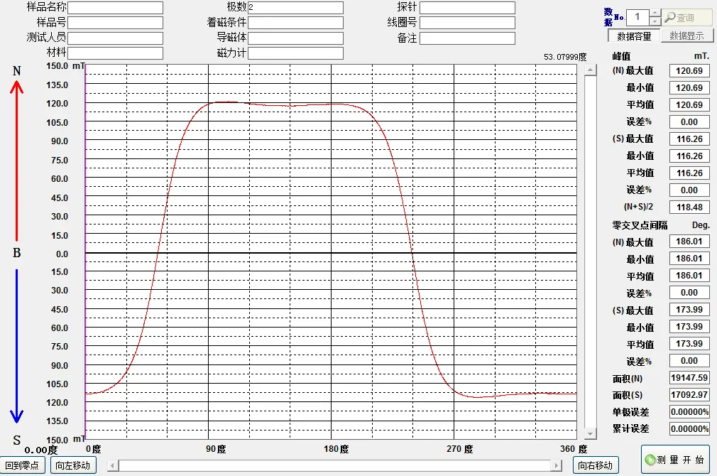
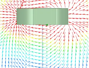
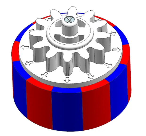
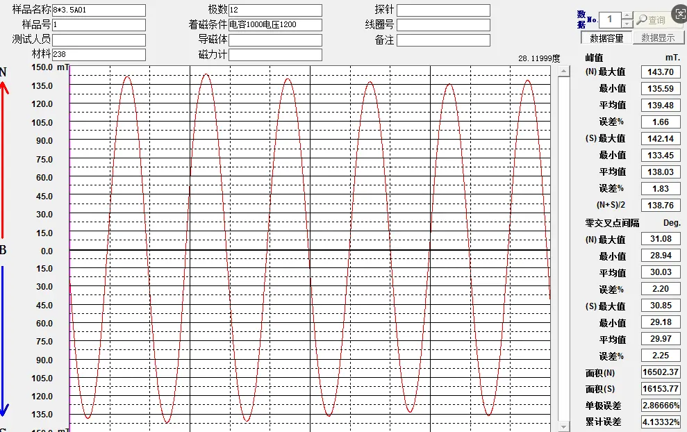
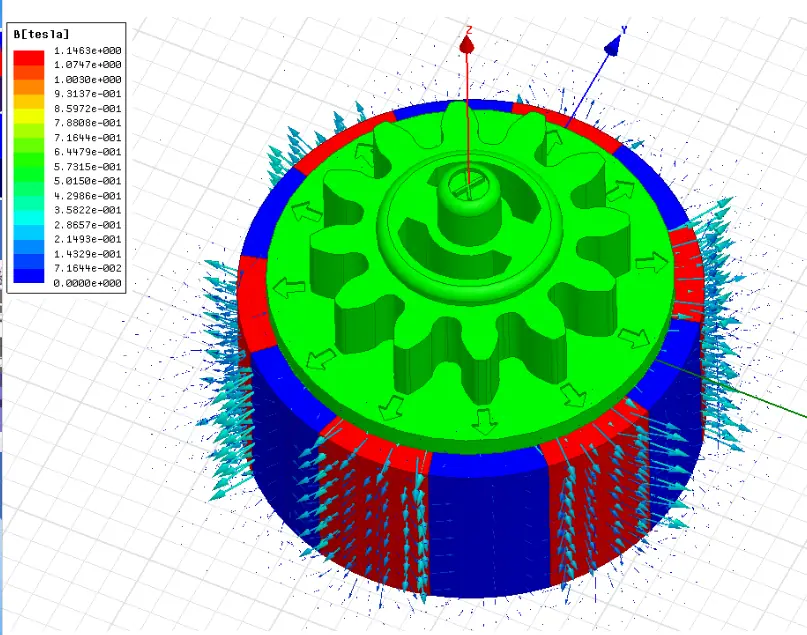
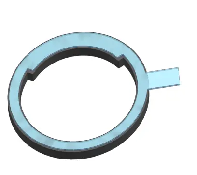
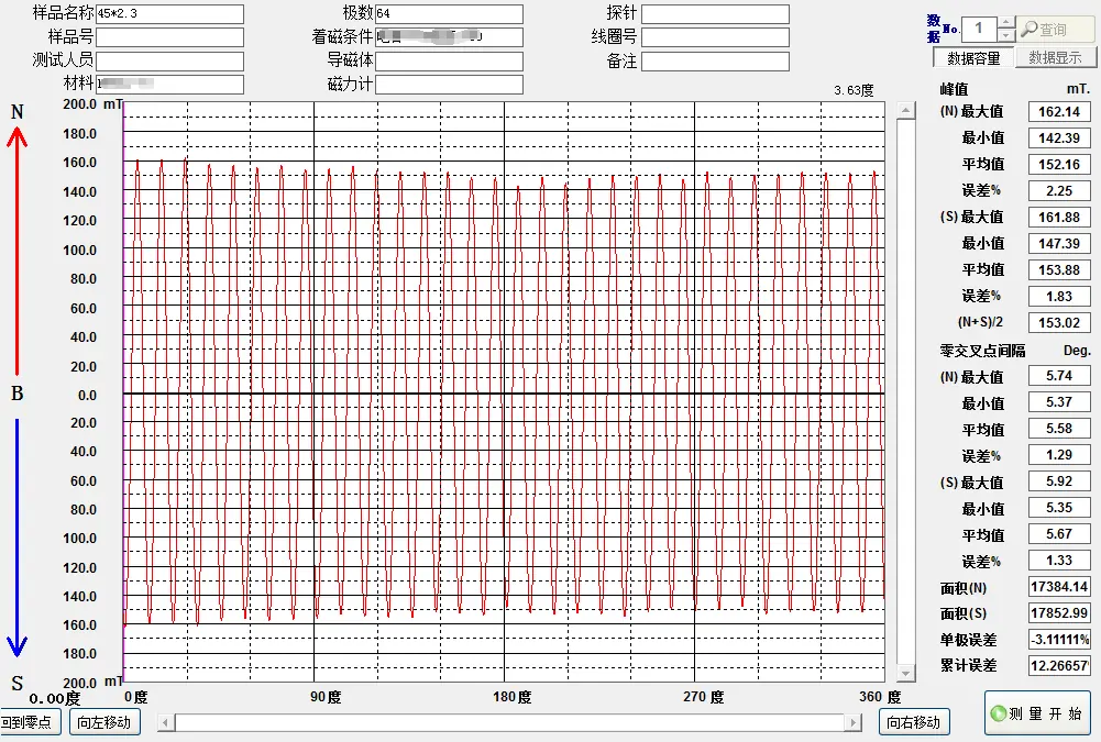
These examples show how bonded magnet materials, molded structures, magnetization patterns and inspection methods are adapted to the functional requirements of each application.

Manufacturing route
Compound selection, molded geometry, inserts, magnetization and inspection are managed against one approved rotor specification.

The drawing, motor type, magnetic target, pole map, speed, operating environment and demand are reviewed together.
Bonded ferrite or bonded NdFeB and the binder system are evaluated against the application requirements.
The parting line, molding shrinkage, insert retention, gate locations and critical datums are defined.
The magnetic body and approved insert structure are produced under controlled process conditions.
The pole pattern, field waveform, dimensions, runout and agreed mechanical characteristics are verified.
The approved drawing, sample, process parameters and inspection plan govern recurring production.
Verification
The inspection plan links the molded magnetic body and insert geometry to pole position, runout, retention and the rotor’s intended function.

| Inspection item | Control method | Purpose |
|---|---|---|
| Molded dimensions | Critical dimensions, bore, OD, datums and insert position checked using the agreed methods | Controls mechanical fit and air-gap consistency |
| Concentricity / runout | Magnetic surface and shaft or insert datums evaluated where specified | Supports stable rotation |
| Magnetic output | Magnetic flux, field waveform or an agreed functional characteristic measured under defined conditions | Verifies the compound and magnetization process |
| Pole position | Pole count, sequence and circumferential position verified against the approved pole map | Helps prevent commutation errors |
| Retention / appearance | Insert security, cracks, flash, joints and contamination evaluated to the agreed criteria | Reduces mechanical and assembly risks |
Applications
Bonded magnet rotors suit projects requiring controlled multipole magnetization, compact geometry, integrated inserts or repeatable magnetic positioning.
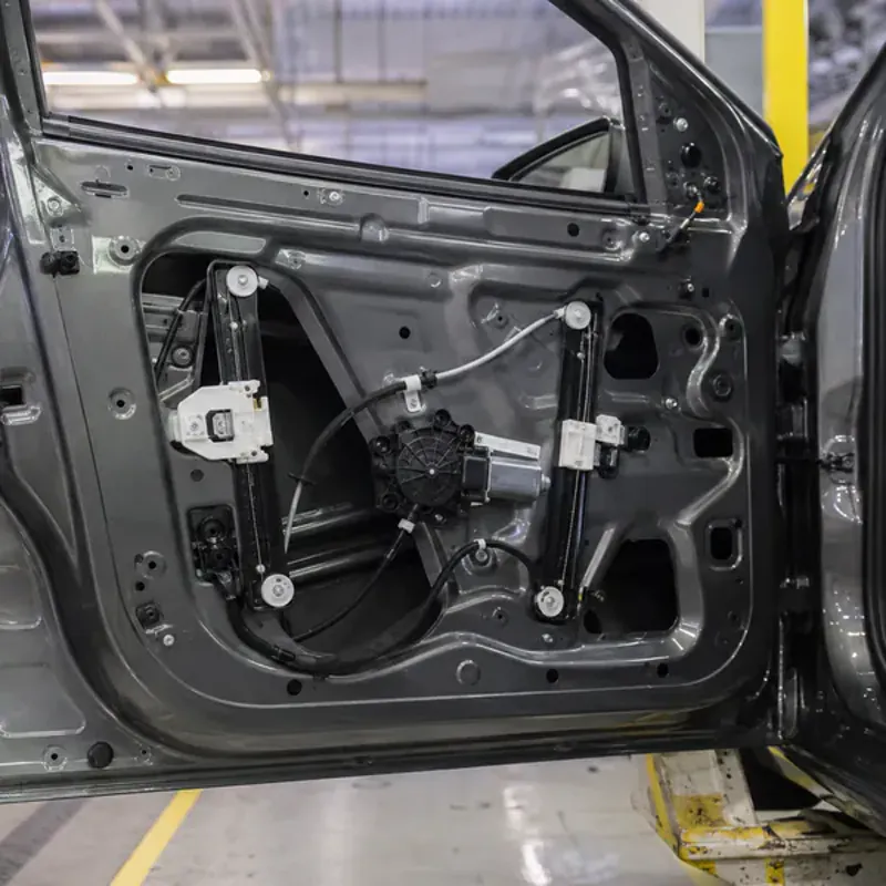
Compact rotors evaluated for pole position, operating temperature, insert retention and recurring production requirements.
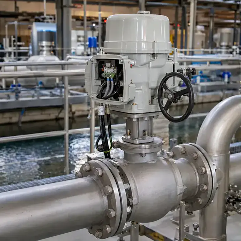
Moisture and chemical exposure, sealing interfaces, operating speed and magnetic response are defined for each project.
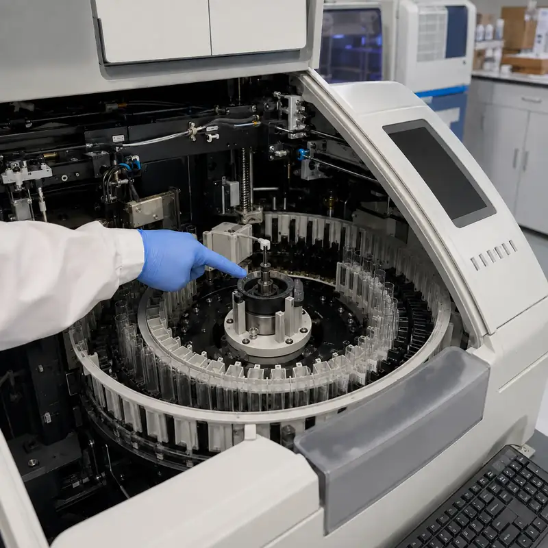
Pole pitch, field waveform, concentricity and the installed air gap form the basis for acceptance.

Rotor geometry, multipole magnetization, runout and fit with the mating stator are reviewed together.
Quality-system support
Drawing revision control, material-lot traceability, sample approval and project-specific inspection planning form the quality framework from incoming materials through finished-product shipment. Statistical process control (SPC), measurement-system analysis (MSA) and process-capability studies (Cpk) are applied to agreed critical characteristics to support dimensional consistency, stable magnetic output and assembly reliability from prototype validation through recurring production.
Magnet geometry, geometric tolerances—including coaxiality, radial or total indicated runout (TIR), and cylindricity—pole layout, pole-to-pole variation, magnet retention and visual standards are controlled to the latest customer-approved drawing revision.
Before recurring production is released, the project provides a full dimensional inspection report (FAI), magnetic test report, material Certificate of Analysis (COA), visual limit samples and process-capability data (Cpk).
Before production begins, the control plan, inspection work instructions, measurement methods and equipment, AQL sampling level and acceptance criteria are confirmed with the customer.
Project-specific inspection records and magnetic-performance data can be provided during sample approval or project review, based on the approved drawing and agreed acceptance criteria.
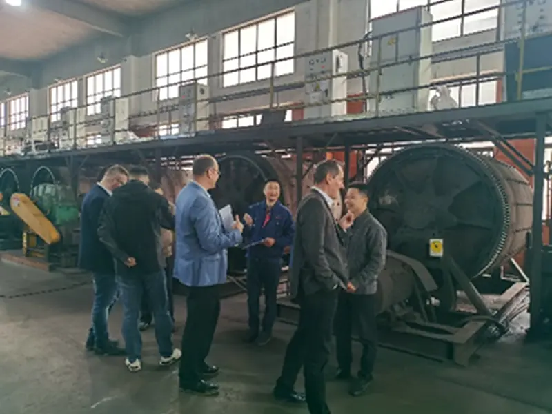
Technical consultation
At industrial exhibitions, GX Magnet presents magnetic materials, rotor assemblies and motor-component capabilities to OEM buyers, engineers and sourcing teams.
Bring your bonded magnet rotor drawing and information about the mating components. An initial discussion can clarify the supply boundary, identify interface risks and establish the information needed for a formal engineering review.
Compare magnet layouts, shaft or hub interfaces and rotor designs before selecting the most suitable quotation route.
Review the air gap, speed, runout, balance, operating environment and validation requirements.
Plan the drawing review, sample approval, inspection records and communication for recurring production.
GX Magnet
GX Magnet’s integrated manufacturing resources combine ferrite-material experience, bonded magnet production and drawing-based rotor project support for automotive, appliance, pump, HVAC and industrial applications.
The magnet material, pole layout, rotor structure and retention method are evaluated against the application requirements.
Mechanical interfaces, approved samples and inspection criteria are controlled against the released drawing revision.
Engineering and sourcing teams receive a clear RFQ checklist and a project-specific definition of the supply scope.
FAQ
Clarify the drawing, material, interfaces, validation requirements and production basis before approving a custom bonded rotor source.
A bonded magnet rotor is often considered when the design requires complex geometry, thin sections, integrated inserts, controlled multipole positioning or fewer secondary assembly operations. The available magnetic output, operating temperature and mechanical requirements must still be evaluated against the motor specification.
The choice depends on the required magnetic output, operating temperature, moisture or chemical exposure, rotor volume, mechanical load and cost target. GX evaluates the magnetic compound and binder system against the application rather than selecting a material by product name alone.
Yes, subject to a review of the insert material, surface condition, knurl or undercut, wall thickness, molding shrinkage, torque transfer, runout datum and retention requirements. The insert drawing is required for quotation.
The pole count, magnetization direction, circumferential pole position and agreed field waveform or magnetic response can be controlled against an approved pole map, measurement fixture, air gap and reference sample.
Critical dimensions must reference a clear datum system. Tooling compensation, insert positioning, process control and sample measurements are then aligned with the bore, OD and working air-gap surfaces.
Provide the continuous and peak temperatures, duty cycle, moisture or fluid exposure, relevant chemicals, storage conditions and required validation tests. These factors affect the magnetic compound, binder, insert interface and test plan.
Define the rated speed, maximum or overspeed condition, torque load, temperature and acceptance criteria. GX can then evaluate a project-specific retention and mechanical validation plan before sample approval.
Send 2D/3D drawings, the magnetic target, preferred material if known, pole map, insert or shaft drawing, critical datums and tolerances, operating speed and environment, sample quantity and estimated annual demand.
Tooling design and fabrication usually take 3 to 5 weeks, depending on the complexity of the mold and inserts. Initial samples are typically provided shortly after tooling completion for your evaluation and approval.
It depends on the operating speed and application. While the molding process offers excellent uniformity, high-speed applications may still require dynamic balancing. We can incorporate balancing features into the mold design or perform post-molding balance correction if specified.
Request for quotation
Include the rotor drawing, bonded material target, pole layout, insert or shaft interface, operating speed and environment, sample quantity and estimated annual demand.